Heat supply network balancing system

A technology for balancing the system and heating network, applied in the field of thermal energy saving, can solve problems such as charging difficulties, uncomfortable room temperature, and low thermal energy conversion efficiency, and achieve the effects of reducing investment and heat loss, reducing return water temperature, and low renovation cost

Inactive Publication Date: 2015-04-29
董全意
View PDF6 Cites 11 Cited by
  • Summary
  • Abstract
  • Description
  • Claims
  • Application Information

AI Technical Summary

Problems solved by technology

[0002] The common problem in the current heating network is that the water supply end of the heating station pays a lot of heat, but the building is unevenly cooled and heated, the room temperature is uncomfortable, the users are not satisfied, and it is difficult to charge
In order to solve the problem, the heat exchange station is forced to operate with a small temperature difference and a large flow rate, resulting in low heat conversion efficiency and high power consumption of the circulating water pump
Therefore, the automatic control equipment such as the automatic temperature control system and the frequency converter in the heat exchange station cannot exert their energy-saving function and potential due to the "barrel effect" of the secondary network of the heating network, the heat supply of automatic climate compensation cannot be realized, and the circulating water pump cannot Cannot run automatically with variable frequency according to actual needs
The traditional solution is to use balanced valve adjustment, but the heat supply cannot be controlled, the heat cannot be used intelligently, the cycle power saving is limited, and the internal transformation cost of the user is high, which is difficult to realize

Method used


Image

  • Heat supply network balancing system

Examples


Embodiment Construction

[0021] It should be noted that, in the case of no conflict, the embodiments of the present invention and the features in the embodiments can be combined with each other.

[0022] The present invention will be described in detail below with reference to the accompanying drawings and examples.

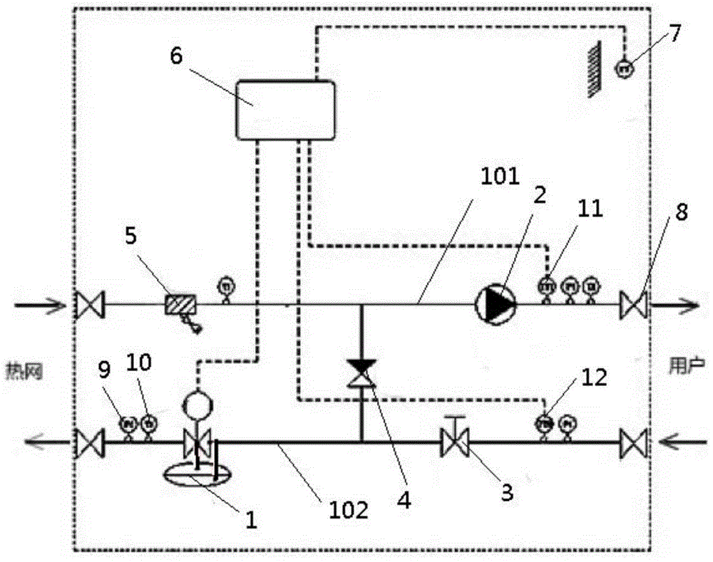
[0023] A heat network balancing system such as figure 1 As shown, it includes a water inlet pipe 101 and a water return pipe 102; the water inlet pipe 101 is sequentially provided with a filter 5, a water pump 2, and a user-side water inlet temperature sensor 11 according to the water flow direction; the water return pipe 102 is sequentially arranged according to the water flow direction User-side return water temperature sensor 12, manual balancing valve 3 and differential pressure control valve 1 with flow adjustment function; check valve 4 is provided between the water inlet pipe 101 and return water pipe 102; the water pump 2 is provided with frequency conversion An outdoor temperat...


PUM


Abstract

The invention discloses a heat supply network balancing system. The heat supply network balancing system comprises a water inlet pipe and a water return pipe; the water inlet pipe is provided with a filter, a water pump and a water inlet temperature sensor at a user side in sequence according to the water flow direction; the water return pipe is provided with a water return temperature sensor at the user side, a manual balance valve and a pressure difference control valve with a flow rate adjusting function in sequence according to the water flow direction; a check valve is arranged between the water inlet pipe and water return pipe; the water pump is provided with a transducer; the pressure difference control valve, water inlet temperature sensor at the user side, water return temperature sensor at the user side and outdoor temperature sensor are connected with a controller with a weather compensation function through circuits; each of the water inlet pipe and water return pipe is provided with a thermometer and a pressure gauge, and shut-off valves are arranged at two ends of each of the water inlet pipe and water return pipe. The heat supply network balancing system realizes the variable-flow rate intelligent heat usage of a secondary network of the heat supply network, the return water at the user side is mixed with the primary side inlet water of the system, the return water energy of the user side is completely used, the comfort is improved for the user, and the energy conservation and environment protection are realized.

Description

technical field [0001] The invention belongs to the technical field of heat energy saving, and in particular relates to a heat network balance system. Background technique [0002] The common problem in the current heating network is that the water supply end of the heating station pays a lot of heat, but the building is unevenly cooled and heated, the room temperature is uncomfortable, the users are not satisfied, and it is difficult to charge. In order to solve the problem, the heat exchange station is forced to operate with a small temperature difference and a large flow rate, resulting in low heat conversion efficiency and high power consumption of the circulating water pump. Therefore, the automatic control equipment such as the automatic temperature control system and the frequency converter in the heat exchange station cannot exert their energy-saving function and potential due to the "barrel effect" of the secondary network of the heating network, the heat supply of ...

Claims


Application Information

Patent Timeline
Patent Type & Authority Applications(China)
IPC IPC(8): F24D3/10F24D19/10
Inventor 董全意
Owner 董全意
Why Eureka
Try Eureka