Membrane stress testing device and method

A film stress, testing device technology, applied in the measurement of permanent deformation force through measuring gauges, etc., can solve problems such as affecting measurement accuracy, microstructure deformation, and increasing measurement error.

Inactive Publication Date: 2015-04-29
巫立斌
View PDF6 Cites 7 Cited by
  • Summary
  • Abstract
  • Description
  • Claims
  • Application Information

AI Technical Summary

Problems solved by technology

The direct method is represented by X-ray instrument and micro-Raman spectrometer measurement. This type of method is expensive and is not conducive to widespread use
The indirect method is represented by measuring the deformation of the sample (displacement and curvature change, etc.), such as ring structure, diamond structure and pointer rotation structure to measure the plane displacement of key points, double-end fixed beam array and cantilever beam to measure the out-of-plane displacement of key points , but these methods also have some disadvantages, for example, 1. Due to the deformation of the microstructure itself, the measurement error increases
2. Process errors such as the shape and size of the microstructure, the angle between the support part and the substrate, and over-etching will also affect the measurement accuracy

Method used


Image

  • Membrane stress testing device and method
  • Membrane stress testing device and method
  • Membrane stress testing device and method

Examples


Embodiment Construction

[0025] The present invention will now be further described with reference to the drawings and specific embodiments.

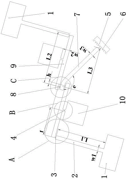
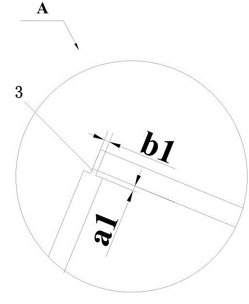
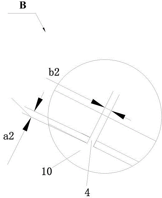
[0026] As a specific example, such as figure 1 As shown, a thin film stress test device of the present invention is prepared on a substrate by ICP etching technology, and includes at least two fixed ends 1 of an axisymmetric design. The two fixed ends 1 include a sacrificial layer formed on the substrate. And the thin film to be tested formed on the sacrificial layer. The number of the fixed ends 1 is 2-4, but this embodiment uses two fixed ends 1. Each fixed end 1 is connected to a fixed beam 2, and the other free end of each fixed beam 2 is fixed by a fixed beam 2. The beam connection neck 3 is connected with one end of a cantilever beam 9 at an included angle, and the range of the included angle is 40°-90°, and 90° is used in this embodiment. The design of different included angles has an impact on the miniaturization and torque balance of the entire product. ...


PUM

PropertyMeasurementUnit
angleaaaaaaaaaa

Abstract

The invention relates to an MEMS (micro electro mechanical systems) testing technique, in particular to a membrane stress testing device and method. The device comprises at least two fixing terminals in symmetrical design; each fixing terminal is connected with a fixing beam; the other free end of each fixing beam is connected with one end of a cantilever beam through a fixing beam connecting neck at an included angle; a pointer beam is clamped between the other ends of the cantilever beams through two cantilever beam connecting necks; the pointer beam is close to one cantilever beam and far away from the other cantilever beam; the pointer beam points to a scale; the scale comprises a sacrificial layer formed on a substrate and a membrane to be tested, formed on the sacrificial layer and is provided with a comb-tooth structure used with the pointer beam to read a swing value of the pointer beam. The method is applied to the device; small displacement of the fixing beams is secondarily amplified into swing displacement of the pointer beam through the cantilever beams, a rotating arm and the pointer beam, the swing displacement is acquired directly through the scale, and residual stress of the membrane is solved through a linear-elastic theory equation.

Description

Technical field [0001] The invention relates to a micro-electromechanical system (EMES) testing technology, in particular to a thin film stress testing device and method. Background technique [0002] Micro-Electro-Mechanical System (MEMS, Micro-Electro-Mechanical System) refers to a micro-device or system that can be manufactured in batches, integrating micro-mechanisms, micro-sensors, micro-actuators, signal processing and control circuits, until the interface, communication and power are equal to one . MEMS is an independent intelligent system whose system size is several millimeters or even smaller, and its internal structure is generally on the order of micrometers or even nanometers. [0003] MEMS is an advanced manufacturing technology platform. It is developed based on semiconductor manufacturing technology. MEMS technology uses a series of existing technologies and materials such as photolithography, corrosion, and thin films in semiconductor technology. [0004] Because...

Claims


Application Information

Patent Timeline
Patent Type & Authority Applications(China)
IPC IPC(8): G01L1/06
Inventor 巫立斌
Owner 巫立斌
Why Eureka
Try Eureka