Method and device for testing thermal contact resistance of joint surfaces between cylindrical sleeve walls

A technology of contact thermal resistance and testing device, which is applied in thermomechanical coupling test and heat transfer field of solid materials, can solve the problems such as the difficulty of testing the contact thermal resistance of the interface between the walls of cylindrical sleeves, and achieve the effect of convenient production

Active Publication Date: 2015-04-29
BEIJING UNIV OF TECH
View PDF10 Cites 10 Cited by
  • Summary
  • Abstract
  • Description
  • Claims
  • Application Information

AI Technical Summary

Problems solved by technology

At present, scholars at home and abroad have carried out a series of researches on the measurement of contact thermal resistance between solid joint surfaces. The common experimental object is to study the measurement methods and devices for the contact thermal resistance of simple joint surfaces between long axes or cuboids. The steady-state test method collects the temperature at different points on the sample axis, and calculates the contact thermal resistance of the contact interface between the two test pieces according to the one-dimensional steady-state heat conduction characteristics in the flat wall. Higher requirements, usually only the test specimen can be prepared into a regular long axis or cuboid, and it is difficult to test the contact thermal resistance of the interface between the walls of the cylindrical sleeve

Method used


Image

  • Method and device for testing thermal contact resistance of joint surfaces between cylindrical sleeve walls
  • Method and device for testing thermal contact resistance of joint surfaces between cylindrical sleeve walls
  • Method and device for testing thermal contact resistance of joint surfaces between cylindrical sleeve walls

Examples


Embodiment 1

[0018] The first step, preparation of test specimens and equipment

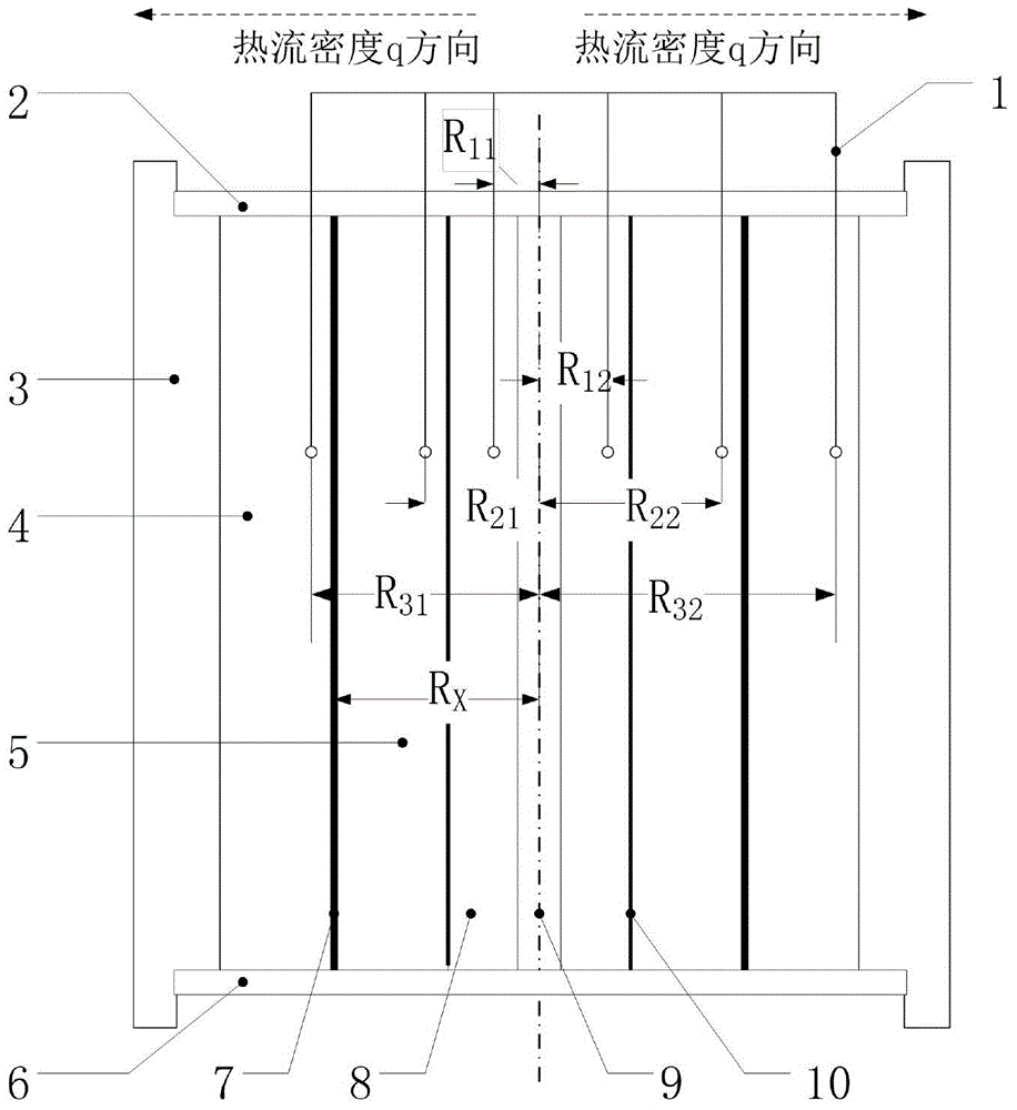
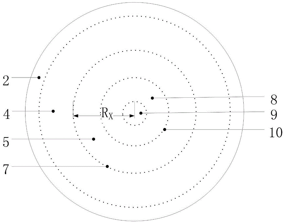
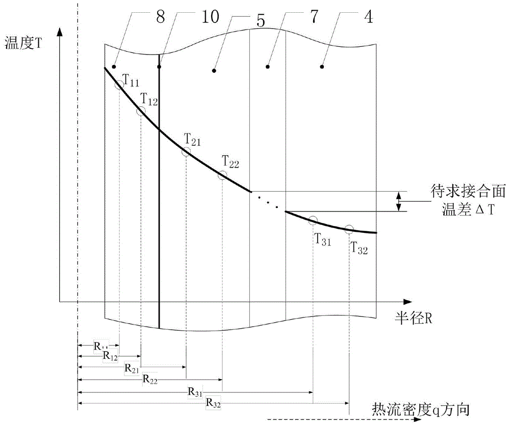
[0019] Take two cylindrical test pieces that are in contact with each other and have a certain thickness, that is, the outer ring test piece 4 and the inner ring test piece 5; process a calibrated copper ring heat flow meter 8 and place it inside the inner ring test piece 5 to closely fit it . The upper and lower axial ends of the entire test device are respectively provided with an upper heat insulation device 2 and a lower heat insulation device 6 to ensure that the heat flow direction propagates along the radial direction. A heating device is arranged inside the calibration copper ring heat flow meter 8, and a cooling ring 3 is arranged outside the outer ring test piece 4 to form a temperature gradient. Temperature sensors 1 are installed at different radii of the calibrated copper heat flow meter 8 , at different radii of the inner ring test piece 5 , and at different radii of the outer ring test piece 4...

Embodiment 2

[0060] The difference from Example 1 is that in this example, the materials of the two test pieces, the temperature values ​​of each measuring point, and the matching relationship are kept consistent at a certain value, and the roughness Ra of the surface of the test piece is changed, and then each roughness Ra is obtained by calculation. The contact thermal resistance R of the cylinder sleeve wall under different surface roughness Ra is obtained through numerical fitting to obtain the relationship between the contact thermal resistance R of the joint surface between the cylindrical sleeve walls under different surface roughness Ra when the test piece material, the temperature value of the measuring point, and the matching relationship are constant.

Embodiment 3

[0062] The difference from Embodiment 1 and Example 2 is that in this embodiment, the materials of the two test pieces, the temperature values ​​of each measuring point, and the roughness Ra of the surface of the test piece are kept consistent at a certain value, and the matching relationship between the walls of the cylindrical sleeve is changed. Then, the thermal contact resistance R under different matching relationships can be obtained by calculation, and the material of the test piece, the temperature value of the measuring point, and the roughness Ra of the surface of the test piece can be obtained through numerical fitting. The relationship between the surface contact thermal resistance R.


PUM


Abstract

The invention provides a method and a device for testing the thermal contact resistance of joint surfaces between cylindrical sleeve walls. According to the method and the device, an outer-ring test piece, an inner-ring test piece and a calibrated copper ring are orderly nested and connected to each other to create a one-dimensional steady-state heat conduction environment with conduction in the radial direction of the ring-shaped test pieces. Temperature sensors arranged in different radiuses in the radial direction are used for measuring the temperatures in different radiuses of each test piece; the measured temperature values of the two test pieces are fitted by use of a numerical method and pushed out to the contact joint surfaces to obtain temperature drop at the contact joint surfaces; the heat flux density at the contact joint surfaces is obtained by use of the measured temperatures of the calibrated copper ring and according to a radial one-dimensional heat conduction line heat flux density formula per unit length; finally, the thermal contact resistance of contact joint surfaces is obtained on the basis that the thermal contact resistance is the reciprocal of the contact heat conduction; meanwhile, the heat conductivity coefficient of the inner-ring and outer-ring test pieces also can be obtained according to the law of radial one-dimensional heat conductivity coefficients.

Description

technical field [0001] The invention relates to a method and a device for testing the contact thermal resistance of a joint surface between cylindrical sleeve walls, belonging to the technical field of solid material heat transfer and thermomechanical coupling tests. Background technique [0002] When the surfaces of two solid materials are in contact with each other, in fact, the direct contact between solid and solid can only occur in some discrete points or small areas, while most of the rest are air or other media. Due to the microscopic unevenness of the two contact surfaces, the contact is not complete, resulting in contact thermal resistance. In the mechanical structure, the contact thermal resistance is one of the very important parameters. The accuracy of its value is directly related to the quality of each design and structure, and its size is related to the efficiency of heat transfer inside each structure. At present, scholars at home and abroad have carried out...

Claims


Application Information

Patent Timeline
Patent Type & Authority Applications(China)
IPC IPC(8): G01N25/20
Inventor 刘志峰马澄宇赵永胜
Owner BEIJING UNIV OF TECH
Why Eureka
Try Eureka