Electronic toll collection system and method

An electronic non-stop and toll collection system technology, applied in the field of highway toll collection, can solve the problems of unreliable video capture results of electronic label installation, and the reliability and accuracy cannot meet the requirements of lane inspection, so as to avoid following interference and neighbors. channel interference, realize automatic matching, and avoid the effect of erroneous and omission charging

Inactive Publication Date: 2015-04-29
北京速通科技有限公司
View PDF6 Cites 63 Cited by
  • Summary
  • Abstract
  • Description
  • Claims
  • Application Information

AI Technical Summary

Problems solved by technology

In this invention, the roadside unit RSU and the camera are two separate devices, and the information matching of the two devices by the lane control unit is carried out after the transaction is completed. Reliable, the reliability and accuracy of after-the-fact evidence collection cannot meet the requirements of lane inspections

Method used


Image

  • Electronic toll collection system and method
  • Electronic toll collection system and method
  • Electronic toll collection system and method

Examples


Embodiment 1

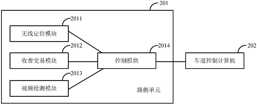
[0084] Figure 4 It is a schematic diagram of the composition and interface of the roadside unit in the embodiment of the present invention. The data interface between the internal modules of the roadside unit adopts the serial communication interface RS485 protocol, which supports high-speed data transmission of multiple terminals. In order to match at the time node, the control module sends a synchronization command through a general-purpose programmable I / O port (General-Purpose Input / Output Ports, GPIO port for short), and provides a reference clock signal to other devices to obtain multiple devices in the same Moments of location and transaction information.

[0085] The RS485 interface protocol format can be (921600, N, 8, 1), that is, the baud rate is 921600bps, no parity check, 8 data bits, and 1 stop bit format. The data frame format of the vehicle position information output by the video detection module is shown in the following table:

[0086] Table 1 Data frame...

Embodiment 2

[0118]The main difference between this embodiment and Embodiment 1 is that the video detection module adopts a binocular camera, which can calculate the three-dimensional information of the vehicle, thereby identifying the vehicle type. Vehicle type is one of the important basis for expressway toll collection. Real-time identification of vehicle type can prevent the electronic tag from being misappropriated to vehicles that do not match the original vehicle type, ensuring that the toll amount matches the vehicle type, and avoiding the problem of missing charges.

[0119] A binocular camera refers to a camera that uses a dual-lens method for image capture and video detection. The binocular camera is composed of left and right cameras (it can also be composed of up and down). The difference in the shooting angles of the two cameras will cause the same object to produce two associated images under different viewing angles. After algorithm processing, synthesis and matching, A thr...


PUM


Abstract

The invention discloses an electronic toll collection system and method. The system consists of a lane control computer and a road side unit, wherein the lane control computer is used for receiving information of the road side unit and performing corresponding treatment on the information; the road side unit comprises a wireless location module used for locating a vehicle-mounted e-tag, a toll transaction module used for communicating with the vehicle-mounted e-tag, acquiring billing and vehicle information of the vehicle-mounted e-tag and completing toll transaction, a video detection module used for detecting vehicle positions, capturing vehicle images and recognizing vehicle registration plates, and a control module used for realizing real-time position matching between position information, acquired by the wireless location module, of the vehicle-mounted e-tag and the vehicle position information detected by the video detection module and achieving corresponding process control. According to the invention, the toll transaction success rate can be effectively improved, car-following interference is reduced and toll dodging is prevented.

Description

technical field [0001] The invention relates to the technical field of expressway toll collection, in particular to an electronic non-stop toll collection system and method. Background technique [0002] Expressway Electronic Toll Collection (ETC) system is an advanced cashless automatic toll collection technology that appears with the improvement of the construction of expressways in my country and the increase of vehicle traffic volume, which can improve the traffic capacity of expressways. , and has a significant effect of energy saving and emission reduction. [0003] In the ETC system, the On Board Unit (OBU) is installed on the inner side of the front glass of the vehicle, the road side unit (RSU) of the toll station is installed on the gantry above the ETC lane, and the toll station Lane control computers and related control equipment are installed in the toll booths. When the vehicle passes through the ETC toll lane, the OBU receives the Dedicated Short Range Commun...

Claims


Application Information

Patent Timeline
Patent Type & Authority Applications(China)
IPC IPC(8): G07B15/06
CPCG07B15/06
Inventor 桂杰张北海鲁程李全发王占军杨毓娟薛金银秦建良侯年颖
Owner 北京速通科技有限公司
Why Eureka
Try Eureka