Gas absorbing device for fuel element

A gas absorption and fuel element technology, which is applied to fuel elements, reactor fuel elements, measuring devices, etc., can solve the problems of hydrogen absorption damage to the coating material of fuel elements, small surface area for absorbing hydrogen tritium, and the strength of supporting structures. Risk of hydrogenation and breakage, increased gas absorption volume and surface area, simple effect of processing

Inactive Publication Date: 2015-04-29
SHANGHAI NUCLEAR ENG RES & DESIGN INST CO LTD
View PDF12 Cites 0 Cited by
  • Summary
  • Abstract
  • Description
  • Claims
  • Application Information

AI Technical Summary

Problems solved by technology

Through analysis and calculation, and a lot of operating experience, it is shown that the commonly used tubular support structure can meet the strength requirements, but when the catalyst is coated on its surface to make it have the ability to absorb hydrogen and tritium, due to a large amount of hydrogen absorption, the resulting structure Loose hydrides, which lead to a decrease in the strength of the support structure and therefore may cause instability of the support structure
Moreover, the structure is a tubular structure. If the catalyst is only coated on the inner surface of the tubular structure, the catalyst coating is difficult and difficult to process due to the small inner wall space of the tubul

Method used


Image

  • Gas absorbing device for fuel element
  • Gas absorbing device for fuel element
  • Gas absorbing device for fuel element

Examples


Embodiment 1

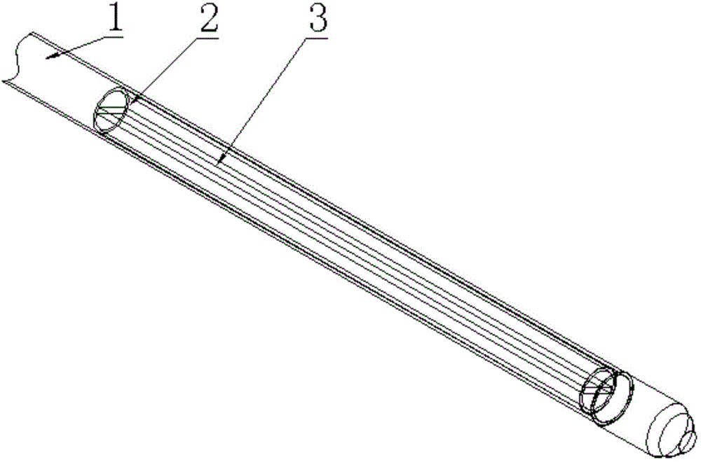
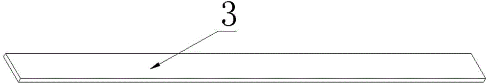
[0025] Such as figure 1 , figure 2 As shown, a fuel element gas absorbing device includes a fuel element coating material 1 with a cylindrical structure and a sheet-shaped gas absorbing structure 3 capable of absorbing hydrogen and hydrogen isotopes, wherein the sheet-shaped gas absorbing structure 3 is a flat plate structure , which is fixed inside the fuel element cladding material 1 through a cylindrical or spiral support structure 2, and a sheet-like gas-absorbing structure 3 is fixed on the upper or lower part of the fuel pellet area of ​​the fuel element; the sheet-like gas-absorbing structure 3 is composed of Hydrogen and hydrogen isotope absorption materials such as zirconium alloys, ceramics or zirconium-aluminum alloys are coated with catalysts such as Ni and Pd on their surfaces.

Embodiment 2

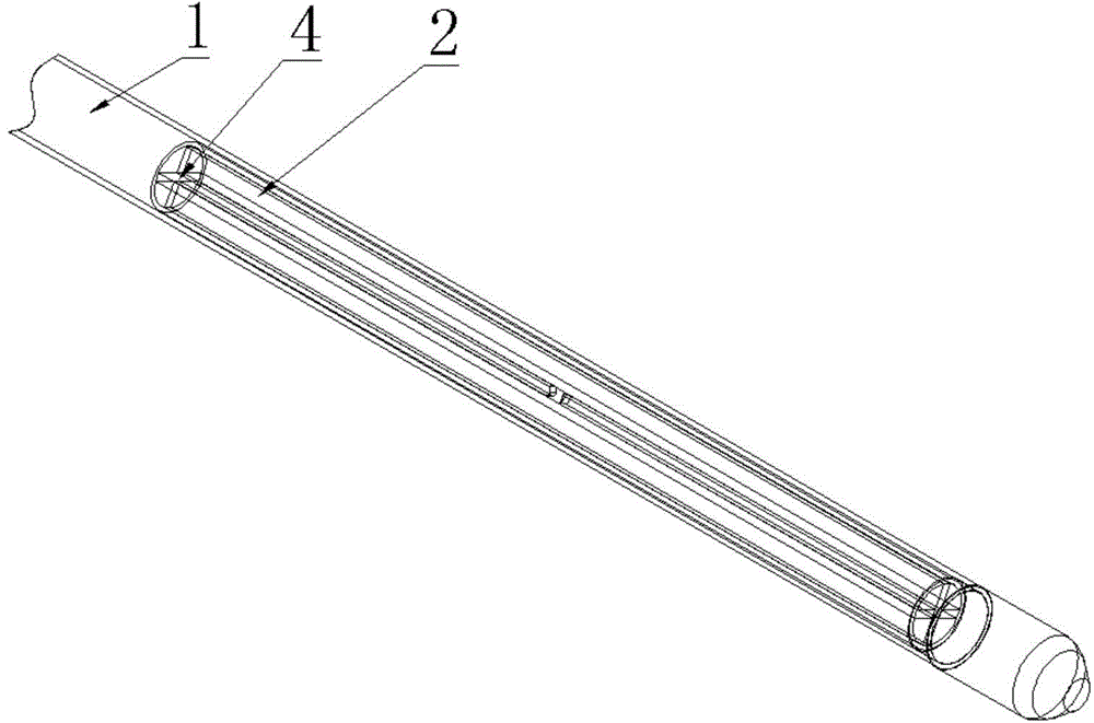
[0027] Such as image 3 , Figure 4 As shown, a fuel element gas absorption device includes a fuel element coating material 1 with a cylindrical structure and a cross-shaped gas absorption structure 4 capable of absorbing hydrogen and hydrogen isotopes, wherein the cross-shaped gas absorption structure 4 is two A cross-shaped plate structure formed by a vertical plate, which is fixed inside the fuel element cladding material 1 through a cylindrical or spiral support structure 2, and a cross-shaped gas absorption structure 4 is fixed on the upper part of the fuel pellet area of ​​the fuel element Or the lower part; the cross-shaped gas absorption structure 4 is made of hydrogen and hydrogen isotope absorption materials such as zirconium alloys, ceramics or zirconium-aluminum alloys, and its surface is coated with catalysts such as Ni and Pd.

Embodiment 3

[0029] Such as Figure 5 , Figure 6 As shown, a fuel element gas absorption device includes a fuel element coating material 1 with a cylindrical structure and a helical gas absorption structure 5 capable of absorbing hydrogen and hydrogen isotopes, wherein the helical gas absorption structure 5 is directly fixed on the Inside the fuel element cladding material 1, the spiral gas absorbing structure 5 is fixed on the upper or lower part of the fuel pellet area of ​​the fuel element; the cross-shaped gas absorbing structure A4 is made of hydrogen and tritium absorbing materials such as zirconium alloy, ceramics or zirconium aluminum alloy , coated with catalysts such as Ni and Pd on its surface.


PUM


Abstract

The invention relates to the technical field of fuel elements, and particularly discloses a gas absorbing device for a fuel element. The gas absorbing device for the fuel element comprises a fuel element coating material adopting a cylindrical case structure as well as a gas absorbing structure which is fixed in the fuel element coating material and can absorb hydrogen and isotopes of hydrogen, wherein the gas absorbing structure is located at the upper or lower part of a fuel pellet zone of the whole fuel element. With the adoption of the gas absorbing device for the fuel element, the content of gases such as the hydrogen, the isotopes of the hydrogen and the like in the fuel element can be decreased, risks of hydrogenation and damage to the cladding of the fuel element are reduced, emission of the isotopes of the hydrogen and pollution are reduced, and meanwhile, adverse effects on the performance of the fuel element can be avoided.

Description

technical field [0001] The invention belongs to the technical field of fuel elements, and in particular relates to a gas absorbing device for fuel elements. Background technique [0002] Typical pressurized water reactor fuel assemblies work under harsh conditions such as high temperature, high pressure, high boron water, strong neutron irradiation, corrosion, erosion and hydraulic vibration in the core for a long time, so the performance of the fuel assembly is directly related to the reactor Safety, reliability, economy and advancement. Pressurized water reactors generally use low-enriched uranium fuel, spring grids, and boxless bundled rod fuel assemblies. The fuel assembly is composed of fuel elements, positioning grids, assembly skeletons and other components, among which the components used to generate nuclear fission and release heat are fuel elements. A typical fuel element is about 3 to 4 meters in length and 9 to 11 mm in outer diameter. It is composed of uranium...

Claims


Application Information

Patent Timeline
IPC IPC(8): G21C3/17G21C3/04
CPCG21C3/041Y02E30/30
Inventor 党宇李继威付亚茹丁阳周勤李怀斌朱丽兵梅其良
Owner SHANGHAI NUCLEAR ENG RES & DESIGN INST CO LTD
Why Eureka
Try Eureka