
Niobium-based manganese-lithium-rich cathode material and preparation method thereof

A technology of niobium-based manganese-rich lithium and positive electrode materials, applied in battery electrodes, electrical components, electrochemical generators, etc., can solve the problems of large irreversible capacity and commercialization restrictions, and achieve simple and easy-to-operate production process and increase reversible capacity , the effect of high structural stability

Inactive Publication Date: 2015-04-29
MCNAIR TECH +1
View PDF3 Cites 3 Cited by
  • Summary
  • Abstract
  • Description
  • Claims
  • Application Information

AI Technical Summary

Problems solved by technology

However, during the first charge and discharge process of this material, Li 2 MnO 3 The irreversible removal of lithium and the absence of oxygen in the middle form Li 2 O, resulting in a larger irreversible capacity for the first time
Therefore, the lithium-rich manganese cathode material xLi 2 MnO 3 ·(1-x)LiMO 2 Commercialization is limited

Method used


Image

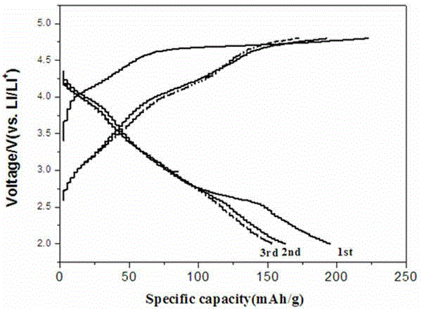
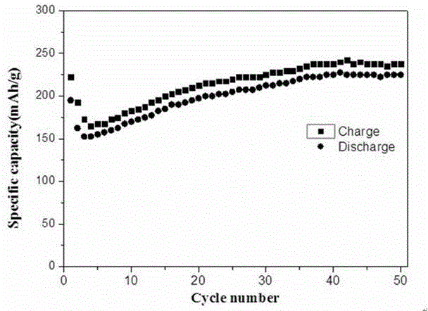
  • Niobium-based manganese-lithium-rich cathode material and preparation method thereof
  • Niobium-based manganese-lithium-rich cathode material and preparation method thereof

Examples


Embodiment 1

[0023] A method for preparing a niobium-based lithium-rich manganese positive electrode material, comprising the following preparation steps:

[0024] A. Put manganese acetate, lithium acetate, and niobium oxalate into a ball mill tank according to the mass ratio of manganese, lithium, and niobium at 0.5:2:0.5, and ball mill at 300 rpm for 4 hours to obtain a mixed precursor;

[0025] B. Place the precursor in a heating furnace, raise the temperature to 500°C at a heating rate of 3°C / min, and keep it warm for 6 hours to obtain a pre-burned precursor;

[0026] C. Grind the pre-burned precursor and press it into tablets, place it in the heating furnace again, raise the temperature to 900°C at a heating rate of 3°C / min, keep it for 16 hours, and cool it to room temperature with the furnace to obtain the niobium-based lithium-rich Manganese material (0.5Li 3 NbO 4 0.5LiMnO 2 ).

Embodiment 2

[0028] A method for preparing a niobium-based lithium-rich manganese positive electrode material, comprising the following preparation steps:

[0029] A. Put manganese carbonate, lithium carbonate, and niobium hydroxide into a ball mill tank according to the ratio of manganese, lithium, and niobium in the amount of 0.7:2:0.3, and ball mill at 400 rpm for 8 hours to obtain a mixed precursor;

[0030] B. Place the precursor in a heating furnace, raise the temperature to 600°C at a heating rate of 2°C / min, and keep it warm for 6 hours to obtain a pre-burned precursor;

[0031] C. Grind the pre-burned precursor and press it into tablets, place it in the heating furnace again, raise the temperature to 1000°C at a heating rate of 2°C / min, keep it for 20 hours, and cool it to room temperature with the furnace to obtain the niobium-based lithium-rich Manganese material (0.3Li 3 NbO 4 0.7LiMnO 2 ).


PUM


Abstract

The invention provides a niobium-based manganese-lithium-rich cathode material and a preparation method thereof. The niobium-based manganese-lithium-rich cathode material is xLi3NbO4.(1-x)LiMnO2, wherein x is smaller than 0.8 and greater than 0. The preparation method comprises the following steps: a, charging a manganese source, a lithium source and a niobium source into a ball-milling tank at the ratio of manganese to lithium to niobium, and carrying out ball-milling at the speed of 200-400r / min for 1-8 hours to obtain a mixed precursor; b, putting the precursor into a heating furnace, heating to 450-700 DEG C at the rate of 2-5 DEG C / min, and carrying out heat preservation for 1-10 hours to obtain a sintering precursor; and c, grinding the sintering precursor, tabletting, and putting into the heating furnace again, heating to 800-1100 DEG C at the rate of 2-5 DEG C / min, carrying out heat preservation and then cooling to a room temperature, so as to obtain the niobium-based manganese-lithium-rich cathode material. The niobium-based manganese-lithium-rich cathode material prepared by the method has high capacity and rate capability, relatively good cycle performance and low cost.

Description

technical field [0001] The invention relates to the technical field of batteries, in particular to a niobium-based lithium-rich manganese cathode material and a preparation method thereof. Background technique [0002] With the shortage of fossil fuel resources and the increasing environmental problems, governments, new energy manufacturing companies and research institutions are devoting themselves to the development of new lithium-ion batteries with high specific energy and good cycle life. Compared with conventional layered LiCoO 2 、LiNi 1 / 3 co 1 / 3 mn 1 / 3 o 2 and other positive electrode materials, lithium-rich manganese positive electrode material xLi 2 MnO 3 ·(1-x)LiMO 2 (M=Co, Mn, Ni) has a higher specific energy and has received a lot of attention. Lithium-rich manganese cathode material xLi 2 MnO 3 ·(1-x)LiMO 2 It has a special structure and charging and discharging mechanism, which makes it show a super high specific capacity during the charging and disc...

Claims


Application Information

Patent Timeline
IPC IPC(8): H01M4/36H01M4/485H01M4/505H01M10/0525
CPCH01M4/36H01M4/485H01M4/505H01M10/0525Y02E60/10
Inventor 杜陈强宋晓娜屈德扬张新河郑新宇李中延唐致远
Owner MCNAIR TECH
Learn More