Electric vehicle charging system and application method thereof

A charging system and electric vehicle technology, applied in electric vehicles, battery circuit devices, collectors, etc., can solve the problems that the charging device cannot continue to charge automatically, affect the promotion of electric vehicle charging systems, and affect the work and life of electric vehicle owners. Prevention of failure, low cost, powerful effect

Active Publication Date: 2015-04-29
江苏琦龙科技有限公司
View PDF7 Cites 5 Cited by
  • Summary
  • Abstract
  • Description
  • Claims
  • Application Information

AI Technical Summary

Problems solved by technology

[0003] However, the existing electric vehicle charging system has poor anti-interference ability, high failure rate, and cannot be automatically controlled and managed
If there is a sudden power outage during the charging process, the charging device cannot automatically continue charging when the power supply is restored, so that the electric vehicle has not been charged with enough power and cannot be used when it is used, affecting the normal work and life of the electric vehicle owner.
In addition, the existing electric vehicle charging system uses a programmable logic controller, which is costly and prone to scrapping due to frequent failures, which further affects the promotion of electric vehicle charging systems

Method used


Image

  • Electric vehicle charging system and application method thereof
  • Electric vehicle charging system and application method thereof
  • Electric vehicle charging system and application method thereof

Examples


Embodiment Construction

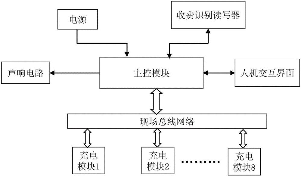
[0039] The structural block diagram of the embodiment of the electric vehicle charging system is as follows: figure 1 As shown, including the main control module and 8 charging modules connected to it, the number of charging modules can be selected for each charging system according to needs. The main power supply is connected to the main control module to supply power for each component. The main control module of the charging system is connected to each charging module through a field bus, and each charging module is given a unique number, which is charging module 1 to charging module 8 in this example. The main control module is also connected with the human-computer interaction interface, the toll identification reader-writer and the sound circuit.

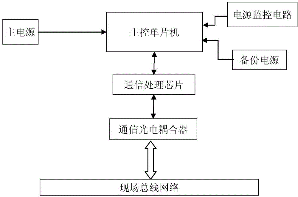
[0040] Such as figure 2 As shown, the main control module of this example is the main control microcontroller, which is connected to the backup power supply, power monitoring circuit, communication processing chip and commu...


PUM


Abstract

The invention discloses an electric vehicle charging system and an application method thereof. The main control module of the charging system is connected with a plurality of charging modules with identification numbers in a wired or wireless manner, and further connected with a human-computer interaction interface and a charging identification reader-writer. The single chip of each charging module is connected with a plurality of charging output ends with specific numbers by use of driving optical couplers and relays. Once a relay is connected, the corresponding charging output end of the relay is connected with a power source. The output end of a current/voltage sampling circuit which is connected with the output end of each relay is connected to the single chip of the corresponding charging module. The application method comprises the following steps: the battery of a user is connected to the selected charging output end, a main control module enables the charging output end to be electrified temporarily, the charging fee needed by the battery is calculated, and then the user pays before charging. The main control module is used for monitoring the charging process, gives an alarm on abnormal circuit opening and an alarm on overcurrent or undervoltage power failure, and controls automatic stop after full charging. The electric vehicle charging system is stable and reliable in operation and high in anti-jamming capability; the user can complete paid charging through self-service; the system can be established into stations of different scales and is easy to expand.

Description

technical field [0001] The invention relates to electric vehicle charging technology, in particular to an electric vehicle charging system and a use method. Background technique [0002] The severe situation of global oil resources and environmental protection makes people prefer non-polluting and convenient electric energy. It is the general trend that electric vehicles replace fuel vehicles, and with the continuous advancement of battery technology and electric motor technology, electric vehicles have become an increasingly cheap, convenient and practical means of transportation, and are becoming increasingly popular. In order to ensure the normal use of electric vehicles, the problem of charging must be solved. Now there are many charging stations for electric vehicles on the streets, and in the future, charging stations will be the same as gas stations, spreading all over urban and rural areas. [0003] However, the existing electric vehicle charging system has poor an...

Claims


Application Information

Patent Timeline
Patent Type & Authority Applications(China)
IPC IPC(8): H02J7/00H02J9/06H02H7/00G07F15/06
CPCG07F15/06H02J7/0013H02J9/06
Inventor 郑伟雄
Owner 江苏琦龙科技有限公司
Why Eureka
Try Eureka