Permanent magnetic direct-current brushless motor of biased mounting structure
An installation structure, permanent magnet DC technology, applied in electric vehicles, synchronous motors with stationary armatures and rotating magnets, motors, etc., can solve the size restrictions of the built-in magnetic ring and stator assembly, which affect the service life of the motor , Motor insulation performance reduction and other issues, to achieve the effect of improving the dustproof and waterproof function, increasing the service life and increasing the load capacity
- Summary
- Abstract
- Description
- Claims
- Application Information
AI Technical Summary
Problems solved by technology
Method used
Image
Examples
Embodiment 1
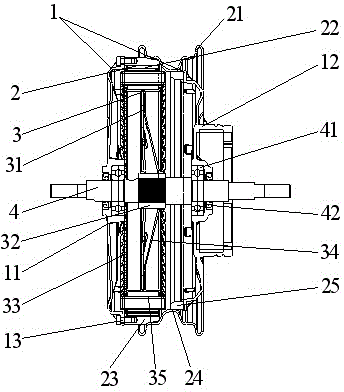
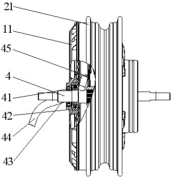
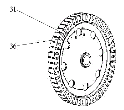
[0026] According to the above-mentioned overall structure, the optimal pole slot ratio of the rotor assembly and the stator assembly of the present invention is 48 poles and 54 slots, and the use of 48 pole permanent magnets can reduce the iron loss of the motor and obtain excellent overall efficiency. Combining the current density of the winding and the iron The maximum magnetic field density of the core adopts the best 54 slot structure, and the slot surface area adopts 75~90mm 2 , the structure ratio improves the overall efficiency of the motor, and has the characteristics of high-speed type.
Embodiment 2
[0028] According to the above-mentioned overall structure, the optimal pole slot ratio of the rotor assembly and the stator assembly of the present invention is 60 poles and 54 slots, and the use of 60 poles permanent magnets can reduce the positioning torque of the motor and obtain an excellent overall torque effect. Combined with the winding current density The best 54-slot structure is selected for the maximum magnetic field density of the iron core, and the slot surface area is 75~90mm 2 , the structure ratio improves the overall efficiency of the motor, and has the characteristics of torque type.
Embodiment 3
[0030] According to the above overall structure, such as Figure 4 As shown, the rim 21 of the present invention can be made of aluminum alloy casting, and the original rim 21 is replaced by the structure of the aluminum alloy rim 5. The middle part of the structure of the aluminum alloy rim 5 is also provided with an aluminum alloy groove bottom 54, which is an asymmetric rounded structure. It has a structure of two rounded corners, one large and one small. The left side of the aluminum alloy rim 5 is provided with a connection platform 51, and the left side of the inner surface of the connection platform 51 is provided with a fixed end cover positioning notch 52 to complete the positioning and installation of the fixed end cover 11. At the same time, the fixed end cover 11 and the left side of the connection table 52 are fastened and connected by fastening screws 53. The inner surface of the connection table 51 is connected with the magnetic guide ring 23, and a fastening tab...
PUM
 Abstract
Description
Claims
Application Information
 - R&D
- Intellectual Property
- Life Sciences
- Materials
- Tech Scout
- Unparalleled Data Quality
- Higher Quality Content
- 60% Fewer Hallucinations
Browse by: Latest US Patents, China's latest patents, Technical Efficacy Thesaurus, Application Domain, Technology Topic, Popular Technical Reports.
© 2025 PatSnap. All rights reserved.Legal|Privacy policy|Modern Slavery Act Transparency Statement|Sitemap|About US| Contact US: help@patsnap.com


