Overvoltage-controlled LED constant current circuit

A technology of constant current circuit and overvoltage, applied in electric lamp circuit arrangement, electric light source, lighting device, etc., can solve problems such as affecting the luminous efficiency and service cycle of LED lamp groups, reducing LED luminous efficiency, and damage to multiple LED lamp groups. , to achieve the effect of improving luminous efficiency and service life, reducing changes, and stable circuit operation

Active Publication Date: 2015-04-29
CHANGZHOU XINGYU AUTOMOTIVE LIGHTING SYST CO LTD
View PDF6 Cites 3 Cited by
  • Summary
  • Abstract
  • Description
  • Claims
  • Application Information

AI Technical Summary

Problems solved by technology

When the LED circuit is driven by a triode, as long as the voltage in the LED circuit exceeds a certain value, the multi-channel LED light source it is located in will bear a huge voltage, which will cause greater damage to the multi-channel LED lamp group, thus affecting Luminous efficiency and service life of LED lamp group
During the use of car lights, if one LED does not light up or is damaged, the light distribution will not comply with the regulations; and when the voltage of the LED is too high, the power of the LED where it is located will be too large, thereby reducing the luminous efficiency of the LED.
Although many LED lights currently use overvoltage protection, the circuit structure is relatively complicated

Method used


Image

  • Overvoltage-controlled LED constant current circuit
  • Overvoltage-controlled LED constant current circuit

Examples


Embodiment Construction

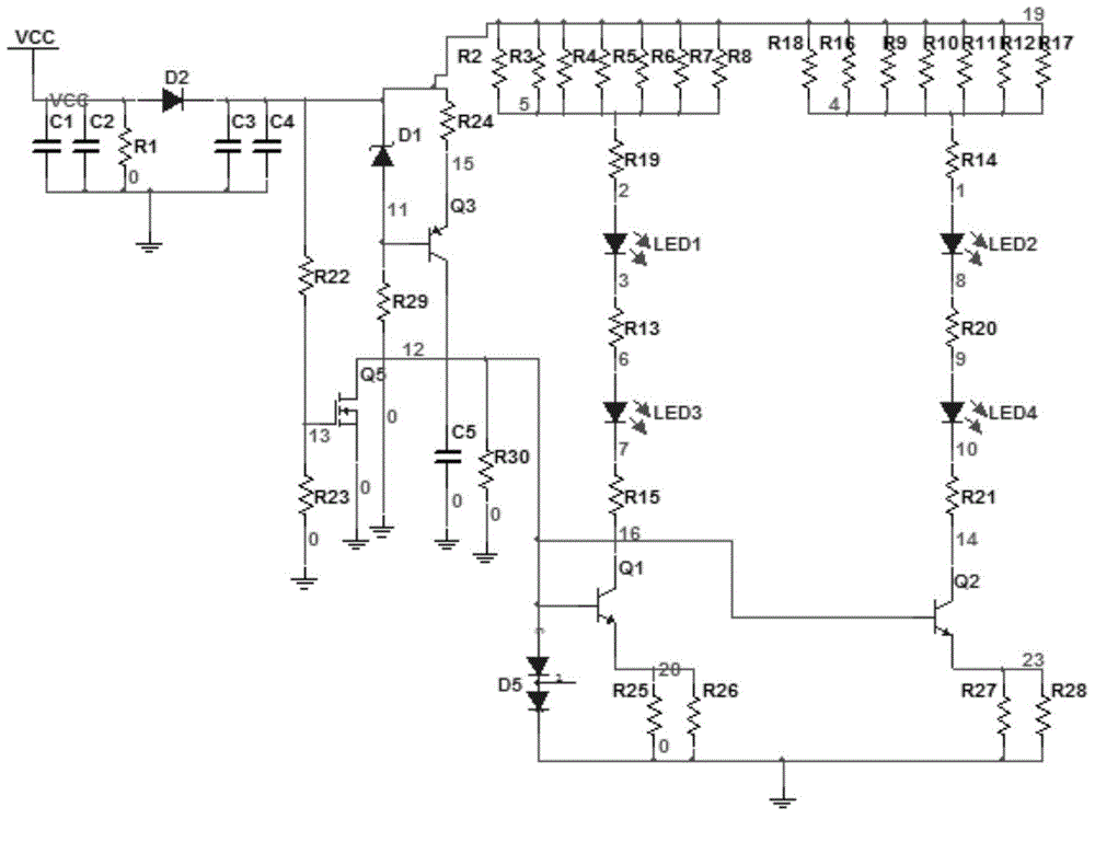
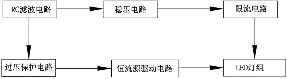
[0010] See figure 1 , 2 As shown, the LED constant current circuit for overvoltage control of the present invention includes an RC filter circuit connected to the input power supply, a voltage stabilizing circuit, a current limiting circuit, an overvoltage protection circuit and a constant current source drive circuit,

[0011] The RC filter circuit of the present invention is a π-type RC filter circuit, and the RC filter circuit includes capacitors C1, C2, C3, C4, resistor R1, and diode D1, and capacitors C1, C2, resistor R1, and capacitors C3, C4 are sequentially connected in parallel to the input power supply Between the diode D1 and the ground, the diode D1 is connected between the resistor R1 and the capacitor C3. Through the RC filter circuit, the LED constant current can be effectively filtered to remove various interferences and noises in the circuit, so that the overall performance of the circuit remains stable.

[0012] See figure 1 As shown, the voltage stabilizin...


PUM


Abstract

The invention relates to an overvoltage-controlled LED constant current circuit. An RC filter circuit is connected with a voltage stabilizing circuit; a first current limiting branch circuit and a second current limiting branch circuit of a current limiting current are connected in series; the first current limiting branch circuit is connected with the voltage stabilizing circuit; the first current limiting branch circuit and the second current limiting branch circuit are respectively connected with a first LED concatenated branch circuit and a second LED concatenated branch circuit; an overvoltage circuit is connected with the RC filter circuit; the grid of an MOS tube Q5 is connected with a junction of a resistor R22 and a resistor R23; the source of the MOS tube Q5 is earthed; the base of a triode Q1 of a constant current source driving circuit is connected with the drain of the MOS tube Q5; the emitter of the triode Q1 of the constant current source driving circuit is connected earthed through a resistor R25; the collector of the triode Q1 of the constant current source driving circuit is connected with the first LED concatenated branch circuit; the base of a triode Q2 is connected with the drain of the MOS tube Q5; the emitter of the triode Q2 is connected earthed through a resistor R27; the collector of the triode Q2 is connected with the second LED concatenated branch circuit; a voltage stabilizing tube D5 is connected between the base of the triode Q1 and the resistor R25. According to the overvoltage-controlled LED constant current circuit, the circuit is simple; the overvoltage protection effect on an LED lamp group can be achieved; the luminous efficiency of the LED lamp group is improved; the service life of the LED lamp group is prolonged.

Description

technical field [0001] The invention relates to an LED constant current circuit controlled by overvoltage, which belongs to the technical field of vehicle lamps. Background technique [0002] As a light source, LED has the advantages of small size, light weight, high light source utilization rate, low power consumption, long service life, short excitation response time, good driving safety, and is conducive to vehicle appearance design. With the rapid development of automobiles , The application of LEDs in car lights is becoming more and more extensive. However, due to its application environment and power supply voltage and current, LEDs will be damaged, and the damage may cause short circuit or open circuit, which cannot meet the light distribution requirements. In order to improve the stability of lighting, in addition to continuously improving the process of LEDs and preventing them from being damaged, the overvoltage control and protection circuits of LEDs are also a h...

Claims


Application Information

Patent Timeline
Patent Type & Authority Applications(China)
IPC IPC(8): H05B37/02
Inventor 徐思阳夏小舟徐从洋
Owner CHANGZHOU XINGYU AUTOMOTIVE LIGHTING SYST CO LTD
Why Eureka
Try Eureka