
Opposed firing structure of boiler

A technology of opposed combustion and boiler, which is applied in the direction of using various fuel combustion, combustion types, combustion equipment, etc., and can solve the problems of increasing boiler maintenance workload, anti-corrosion coating increases the risk of water-cooled wall operation, etc., so as to prevent the occurrence of high-temperature corrosion , Oxygen content increased, the effect of protecting the safety of operation

Active Publication Date: 2015-05-06
XIAN THERMAL POWER RES INST CO LTD
View PDF12 Cites 3 Cited by
  • Summary
  • Abstract
  • Description
  • Claims
  • Application Information

AI Technical Summary

Problems solved by technology

However, this passive protective measure cannot fundamentally solve the problem of high-temperature corrosion. On the contrary, the peeling off of the anti-corrosion coating increases the risk of water-cooled wall operation and increases the workload of boiler maintenance.

Method used


Image

  • Opposed firing structure of boiler
  • Opposed firing structure of boiler
  • Opposed firing structure of boiler

Examples


Embodiment Construction

[0023] The present invention will be described in further detail below in conjunction with the accompanying drawings.

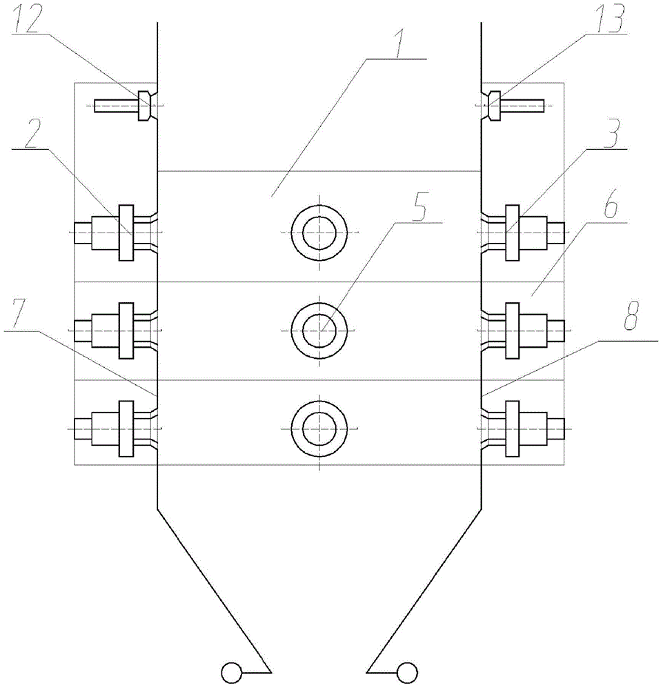
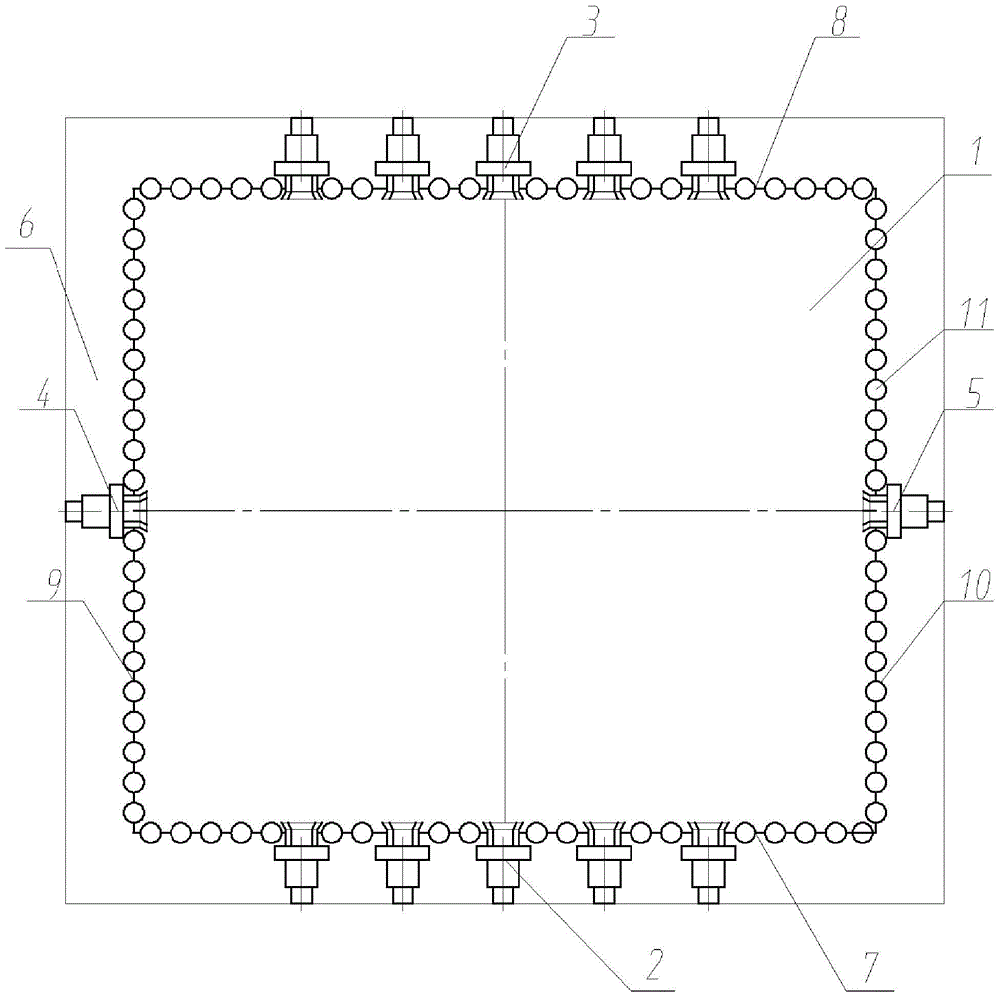
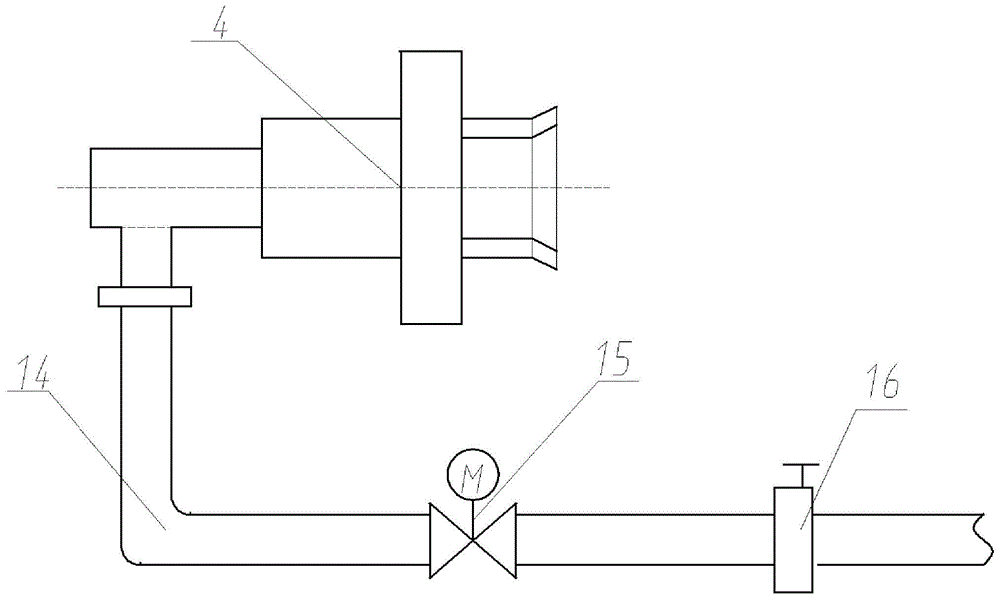
[0024] see Figure 1-2 , the present invention proposes a boiler hedging combustion structure based on the hedging combustion mode of the front and rear walls. The problem of high temperature corrosion of the water wall of the side wall. Including the furnace 1 surrounded by the boiler left wall 9 and the furnace right wall 10, the boiler front wall 7 and the boiler rear wall 8; because the boiler left wall 9 and the boiler right wall 10 are prone to high temperature corrosion, therefore, the boiler left The center line of the wall 9 is arranged along the height direction of the furnace 1 with single or double rows of burners 4 on the left side wall, and the center line of the right wall 10 of the boiler is arranged with single or double rows of burners 5 on the right side wall along the height direction of the furnace 1 In this way, it is possible to form ...


PUM


Abstract

The invention discloses an opposed firing structure of a boiler. The opposed firing structure comprises a hearth, wherein the hearth is formed by enclosing of a boiler left-side wall, a boiler right-side wall, a boiler front wall and a boiler rear wall; left-side wall burners are distributed on the middle line of the boiler left-side wall along the height direction of the hearth; right-side wall burners are distributed on the middle line of the boiler right-side wall along the height direction of the hearth; a plurality of rows of front-wall burners are distributed on the boiler front wall; a plurality of rows of rear-wall burners are distributed on the boiler rear wall; and the peripheries of the boiler left-side wall, the boiler right-side wall, the boiler front wall and the boiler rear wall are provided with bellows for providing secondary air and over-fired air for the hearth. The opposed firing structure disclosed by the invention has the advantage that on the basis of not influencing the original coal-powder burning mode, the problem of corrosion caused by high temperature of water cooling walls of the side walls is thoroughly solved.

Description

technical field [0001] The invention belongs to the field of boilers, and in particular relates to a boiler opposed combustion structure. Background technique [0002] With the large-scale implementation of high-parameter and large-capacity thermal power units, thermal power technology has ushered in new opportunities for development, and at the same time new technical problems have emerged. In order to meet environmental protection emission requirements and reduce the operating pressure of the tail denitrification system, most of the newly commissioned units adopt low-nitrogen combustion technology to control the formation of nitrogen oxides. The low-nitrogen combustion method is to set an overfired air nozzle above the main burner area, and a part of the secondary air is sent into the furnace through the overfired air nozzle. The main burner area is an oxygen-deficient combustion, and the combustion temperature is reduced, thereby suppressing nitrogen oxides. generate. ...

Claims


Application Information

Patent Timeline
Patent Type & Authority Applications(China)
IPC IPC(8): F23C5/28
Inventor 党黎军杨辉张宇博
Owner XIAN THERMAL POWER RES INST CO LTD
Learn More