
A pulverized coal preheater

A preheater and pulverized coal technology, which is applied in the field of pulverized coal preheater, can solve the problems of limited heat exchange time and heat exchange efficiency, difficulty in heating pulverized coal to a predetermined temperature, and affecting boiler heat exchange performance, etc., to achieve improved The effect of service life, reduction of resistance, and increase of residence time

Active Publication Date: 2017-05-24
HANGZHOU XIAOYUE THERMOELECTRICITY
View PDF9 Cites 0 Cited by
  • Summary
  • Abstract
  • Description
  • Claims
  • Application Information

AI Technical Summary

Problems solved by technology

[0005] First of all, due to the problem of gas fluid heat exchange efficiency, the utilization rate of flue gas heat by air preheater is relatively low. When the boiler load is low, it may be difficult for the tail flue gas to raise the air temperature to a predetermined value, and furthermore, it is difficult Heat the pulverized coal to a predetermined temperature;
[0006] Secondly, in different seasons, especially in winter and autumn, the temperature of the pulverized coal itself is relatively low, and it is difficult for a single air preheater to heat the pulverized coal to the predetermined temperature, thus affecting the heat exchange performance of the boiler;
[0007] Finally, when the gas blows the pulverized coal into the furnace, the speed is relatively fast, the heat exchange time and heat exchange efficiency are relatively limited, and sometimes it is difficult to heat the pulverized coal to the predetermined temperature in time

Method used


Image

  • A pulverized coal preheater
  • A pulverized coal preheater

Examples


Embodiment Construction

[0046] The present invention is described in further detail now in conjunction with accompanying drawing. These drawings are all simplified schematic diagrams, which only illustrate the basic structure of the present invention in a schematic manner, so they only show the configurations related to the present invention.

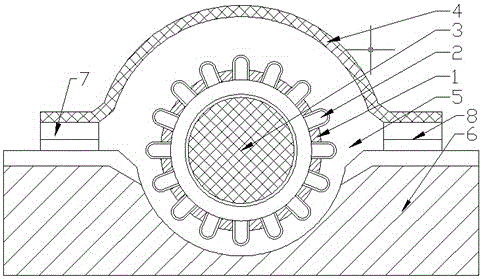
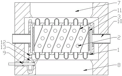
[0047] Such as figure 1 and figure 2 As shown, the present invention is a pulverized coal preheater, including a heating drum 1 and a coal ash flow channel, the coal ash flow channel is composed of a base 6 and an upper cover 4, and the coal ash flow channel includes a 6 a cylindrical cavity 5 between the upper end surface and the upper cover 4, the heating roller 1 is installed in the cylindrical cavity 5, and the two ends of the heating roller 1 and the two ends of the cylindrical cavity 5 pass through the rotating shaft 10 is rotationally connected, and a feed flow channel 7 and a discharge flow channel 8 are also provided between the base 6 and the uppe...


PUM


Abstract

The invention relates to a pulverized coal preheater which comprises a heating roller and a coal ash runner. The coal ash runner comprises a base, an upper cover, and a cylindrical cavity arranged between the upper end face of the base and the upper cover. The heating roller is mounted in the cylindrical cavity. Two ends of the heating roller are rotatably connected with two ends of the cylindrical cavity through rotary shafts. A feed runner and a discharge runner are further arranged between the upper end face of the base and the upper cover. The feed runner and the discharge runner are respectively communicated with the cylindrical cavity. One end of each rotary shaft is fixedly connected with the base. The outer wall at the other end of each rotary shaft is rotatably connected with the end of the heating roller through a bearing. The rotary shafts at two ends of the heating roller are communicated with the interior of the heating roller. The rotary shaft at one end of the heating roller is communicated with a smoke inlet pipe, and the rotary shaft at the other end of the heating roller is communicated with an exhaust pipe. The pulverized coal preheater has the advantages that pulverized coal is heated by the heating roller heated by the tail smoke of a boiler, so that the temperature of the pulverized coal blowing into a hearth can be increased effectively.

Description

technical field [0001] The invention relates to a pulverized coal preheater, which belongs to the auxiliary equipment of a fluidized boiler. Background technique [0002] Fluidized boilers generally blow pulverized coal into the boiler through high-speed airflow to achieve fluidized combustion of pulverized coal. In order to improve the combustion efficiency of the boiler, the high-speed airflow is generally preheated to achieve preheating of pulverized coal , thereby reducing the heat required for pulverized coal to reach the ignition point in the boiler; [0003] The air preheater is commonly used in fluidized boilers as a boiler combustion airflow heating equipment. It mainly uses a partition wall heat exchanger to exchange heat between the flue gas at the tail flue of the boiler and the air before entering the boiler, so as to Improve the heat exchange performance of the boiler and reduce energy consumption; [0004] However, the air preheater also has many problems; ...

Claims


Application Information

Patent Timeline
Patent Type & Authority Patents(China)
IPC IPC(8): F23K1/04
Inventor 叶一中
Owner HANGZHOU XIAOYUE THERMOELECTRICITY
Learn More