
TMX320F28335 floating point DSP (Digital Signal Processor) based two-shaft photoelectric tracking system

A technology of TMX320F28335 and photoelectric tracking system, applied in the direction of using feedback control, etc., can solve the problems of low tracking accuracy, inconvenient installation, disassembly and maintenance, etc., and achieve the effect of improved tracking accuracy, light equipment, and easy installation

Inactive Publication Date: 2015-05-13
HARBIN INST OF TECH
View PDF6 Cites 21 Cited by
  • Summary
  • Abstract
  • Description
  • Claims
  • Application Information

AI Technical Summary

Problems solved by technology

[0004] The purpose of the present invention is to solve the problems of low tracking accuracy and inconvenient installation, disassembly and maintenance in the existing two-axis photoelectric tracking system controlled by DSP. The present invention provides a two-axis photoelectric tracking system based on TMX320F28335 floating-point DSP

Method used


Image

  • TMX320F28335 floating point DSP (Digital Signal Processor) based two-shaft photoelectric tracking system
  • TMX320F28335 floating point DSP (Digital Signal Processor) based two-shaft photoelectric tracking system
  • TMX320F28335 floating point DSP (Digital Signal Processor) based two-shaft photoelectric tracking system

Examples


specific Embodiment approach 1

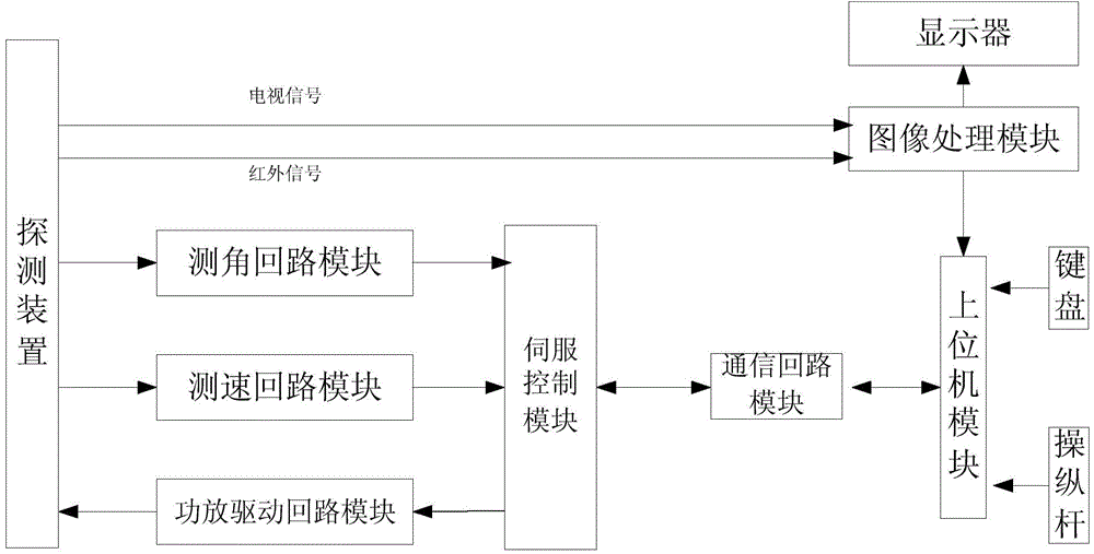
[0040] Specific implementation mode one: combine figure 1 Describe this embodiment, a two-axis photoelectric tracking system based on TMX320F28335 floating-point DSP described in this embodiment, the two-axis photoelectric tracking system includes a detection device, a servo control module, an angle measurement loop module, a speed measurement loop module, a dynamic put drive circuit module, communication circuit module, host computer module and image processing module;

[0041] The detection device is used to use the photoelectric encoder to measure the angle of the pitch axis and the azimuth axis, and use two single-axis fiber optic gyroscopes to measure the angular rate of the azimuth axis and the pitch axis direction respectively; the two single-axis fiber optic gyroscopes are arranged orthogonally ;Use infrared or camera device to collect the image information of the characteristic target; it is also used to receive the driving amount of the pitch axis and the driving amo...

specific Embodiment approach 2

[0056] Specific embodiment two: this embodiment is a further limitation of a two-axis photoelectric tracking system based on TMX320F28335 floating-point DSP described in specific embodiment one,

[0057] The digital PID adjustment algorithm is used in the control of the servo control module. PID adjustment is a control technology with mature technology and wide application in the continuous control system, so it is widely used in various control systems. It is characterized by the formation of a typical structure, convenient parameter setting and adjustment, flexible structure modification, and strong adaptability;

[0058] The output of the controlled quantity of described servo controller module adopts digital PID regulator to regulate, and the mathematical model of described PID regulator is:

[0059] u ( t ) = K p e ( t ...

specific Embodiment approach 3

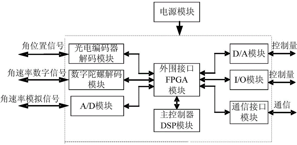
[0069] Specific implementation mode three: combination figure 2 This embodiment is described. This embodiment is a further limitation of the two-axis photoelectric tracking system based on TMX320F28335 floating-point DSP described in Embodiment 1. The servo control module includes a main controller DSP module and a peripheral interface FPGA module , power supply module, photoelectric encoder decoding module, digital gyro decoding module, analog gyro A / D sampling module, D / A module and I / O module; the main controller DSP module is TMX320F28335 floating-point DSP;

[0070] The photoelectric encoder decoding module, digital gyroscope decoding module, analog gyroscope A / D sampling module, D / A module and I / O module perform serial communication with the peripheral interface FPGA module at the same time, and the peripheral interface FPGA module communicates with the main controller DSP module through Parallel bus communication;

[0071] The power module provides working power for t...


PUM


Abstract

The invention provides a TMX320F28335 floating point DSP (Digital Signal Processor) based two-shaft photoelectric tracking system, belongs to the technical field of control of servo movement, and aims at solving the problems of low tracking precision and inconvenient mounting, dismounting and repairing due to the DSP based control for the two-shaft photoelectric tracking system in the prior art. The system comprises a detection device, a servo control module, an angle measuring loop module, a speed measuring loop module, a power amplification driving loop module, a communication loop module, an upper computer module and an image processing module; the angle position information and angle rate information measured by a photoelectric encoder and a gyro of the detection device are respectively sent to the servo control module through the angle measuring loop module and the speed measuring loop module; the image processing module is used for processing the acquired module to obtain the miss distance of a characteristics target; the servo control module is used for acquiring control quantity according to the angle position information, the angle rate information, the miss distance, an instruction of an upper computer and a set working mode and sending to the power amplification driving loop module to drive the detection device to track the characteristics target on real time. The system is applied to the field of military tracking.

Description

technical field [0001] The invention belongs to the field of servo motion control. Background technique [0002] Since the 20th century, control science and engineering have played a pivotal role in the history of human development, and are the key factors to measure the progress of human science and technology. The technological breakthroughs in the field of control have contributed to solving many challenging problems in the world today, and provided scientific thinking methods for the automation of production in many industrial fields. Dynamic target tracking technology is a part of the control field, and it is mainly used in military, aerospace, transportation and other fields, especially in the military field, it has played an important role and achieved success. The photoelectric tracking control system is a key component of tracking, reconnaissance, positioning, navigation and other application fields. Its main technical indicators include load and load weight, size,...

Claims


Application Information

Patent Timeline
Patent Type & Authority Applications(China)
IPC IPC(8): G05D3/12
Inventor 李悦曾庆双
Owner HARBIN INST OF TECH
Learn More