Tunneling field effect transistor and preparation method thereof

A tunneling field effect, transistor technology, applied in semiconductor/solid-state device manufacturing, diodes, semiconductor devices, etc., can solve the problems of small TFET tunneling current, small tunneling area, and low carrier tunneling probability.

Active Publication Date: 2015-05-13
HUAWEI TECH CO LTD
View PDF5 Cites 5 Cited by
  • Summary
  • Abstract
  • Description
  • Claims
  • Application Information

AI Technical Summary

Problems solved by technology

Therefore, in the prior art, the use of a point tunneling mechanism leads to a low probability of carrier tunneling, which makes TFETs have the disadvantage of low tunneling current.
At the same time, the overlapping area between the s

Method used


Image

  • Tunneling field effect transistor and preparation method thereof
  • Tunneling field effect transistor and preparation method thereof
  • Tunneling field effect transistor and preparation method thereof

Examples


Embodiment Construction

[0086] The following will clearly and completely describe the technical solutions in the embodiments of the present invention with reference to the accompanying drawings in the embodiments of the present invention. Obviously, the described embodiments are only some, not all, embodiments of the present invention. Based on the embodiments of the present invention, all other embodiments obtained by persons of ordinary skill in the art without creative efforts fall within the protection scope of the present invention.

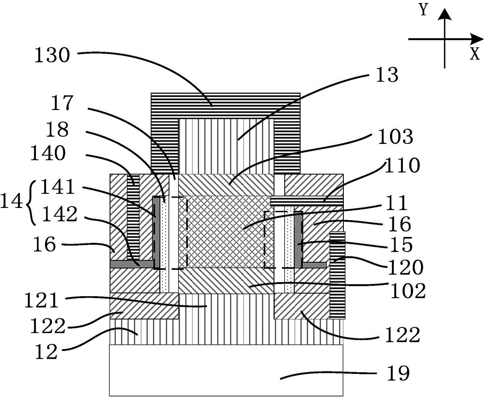
[0087] see figure 1 and figure 2, is a schematic cross-sectional structure diagram of the tunneling field effect transistor provided in the first preferred embodiment of the present invention. The tunneling field effect transistor includes a source region 11 , two drain regions 12 , 13 and two gate regions 14 , 15 . In this embodiment, the first direction Y is the up-down direction relative to the source region 11 , and the second direction X is the left-right d...


PUM


Abstract

Disclosed is a tunneling field effect transistor. The tunneling field effect transistor comprises a source region, two drain regions and two grid regions. The two drain regions are arranged on opposite two sides of the source region in a first direction; the two grid regions are arranged on opposite two sides of the source region; first extension layers and grid medium layers are arranged between the source region and the two grid regions, wherein the first extension layers are arranged between the source region and the grid medium layers and form tunneling junction with the source region; the two drain regions and the two grid regions are arranged around the source region, so that the source region can be completely under the control of the two grid regions, and current carrying electrons in the overlapped regions of the source region and the grid regions can tunnel under the action of the electric field of the grid regions; the first extension layers are arranged between the source region and the grid medium layers and is of a linear tunneling mode, thereby being large in tunneling area; the direction of the electric field of the grid regions and the tunneling direction of the electrons of the source region are on the same line, so that high tunneling probability can be achieved, and tunneling current can be increased. Besides, the invention also provides a preparation method of the tunneling field effect transistor.

Description

technical field [0001] The invention relates to a tunneling field effect transistor and a preparation method thereof. Background technique [0002] Since the birth of the first integrated circuit, integrated circuit technology has been developing along the track of "Moore's Theorem". At present, the size of semiconductor transistors has reached 28nm and 22nm, and the size of transistors will continue to decrease, requiring lower supply voltage and Threshold voltage, but the traditional MOS structure has reached the limit, and the generation of low threshold voltage is becoming more and more difficult. This is because the threshold voltage decreases, and the switching ratio (Ion / Ioff, where Ion is the on-state current, Ioff is the off-state current, the gate voltage is greater than the threshold voltage to obtain Ion, and the gate voltage is less than the threshold voltage to obtain Ioff) will also decrease. resulting in longer switching times. [0003] At the same time, be...

Claims


Application Information

Patent Timeline
IPC IPC(8): H01L29/739H01L29/06H01L21/331
CPCH01L29/06H01L29/739H01L29/7391H01L29/0684H01L29/66356
Inventor 赵静杨喜超张臣雄
Owner HUAWEI TECH CO LTD
Why Eureka
Try Eureka