
Patch antenna for generating vortex electric wave

A patch antenna and radio wave technology, which is applied in the field of antennas, can solve the problems of vortex signal occupying a large space and inconvenient placement, and achieve the effects of miniaturization and miniaturization, simple structure, and easy maintenance

Inactive Publication Date: 2015-05-13
HUAZHONG UNIV OF SCI & TECH
View PDF4 Cites 10 Cited by
  • Summary
  • Abstract
  • Description
  • Claims
  • Application Information

AI Technical Summary

Problems solved by technology

[0005] The invention provides a patch antenna for generating vortex radio waves, which solves the problems of large space occupation and inconvenient placement of vortex signals generated by array antennas

Method used


Image

  • Patch antenna for generating vortex electric wave
  • Patch antenna for generating vortex electric wave
  • Patch antenna for generating vortex electric wave

Examples


Embodiment 1

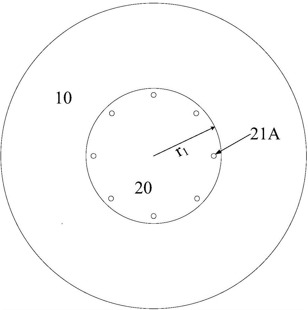
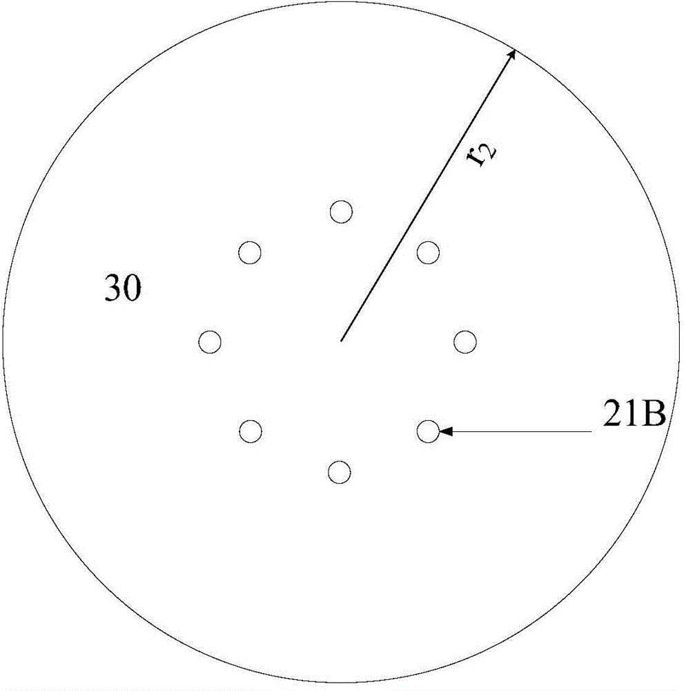
[0027] As shown in FIG. 1(A), FIG. 1(B), and FIG. 1(C), Embodiment 1 of the present invention includes a dielectric substrate 10, a radiation surface 20 and a ground plane 30;

[0028] The dielectric substrate 10 is an insulating dielectric substrate with a circular shape, a radiation surface 20 is pasted on the front, and a grounding surface 30 is pasted on the back of the dielectric substrate 10. The radiation surface 20 is a metal plate with a circular shape. The ground 30 is also a circular metal plate, the centers of the dielectric substrate 10, the radiating surface 20 and the grounding surface 30 coincide, and the radius r of the radiating surface 20 1 is 16mm, the radius r of the ground plane 30 2 is 39.8mm, r 1 = r [ 1 + 2 h πrϵ ( ...


PUM


Abstract

The invention discloses a patch antenna for generating vortex electric wave, belongs to the antenna technical field and solves the problem of the existing array antenna for generating vortex signal of taking big floor space and not convenient to place. The patch antenna for generating vortex electric wave comprises a dielectric substrate, a radiating surface and a grounding plane, the dielectric substrate is the insulating dielectric substrate having round or n-regular polygon shape, the front side is provided with the radiating surface, the back of the dielectric substrate is pasted with the grounding plane, the dielectric substrate, the radiating surface and the grounding plane are overlapped on centres, N feeding ports evenly distributed are arranged along the edge of the radiating surface, and N is greater than or equal to 4. The patch having centimetre-level radius is adopted for generating vortex electric wave different in topological charge, the structure is simple, the volume is small, easy to maintain, convenient for industrial mass production and useful for miniaturization and microminiaturization for vortex communication system.

Description

technical field [0001] The invention belongs to the technical field of antennas, and in particular relates to a patch antenna for generating vortex radio waves. Background technique [0002] With the continuous growth of wireless communication data services, capacity requirements continue to increase, but frequency band resources are limited. The introduction of orbital angular momentum can theoretically break through the capacity bottleneck, which is of great significance for improving the capacity of wireless communication. Orbital angular momentum is a physical property of electromagnetic waves, which reflects the phase change of electromagnetic waves in the azimuth direction around the central axis of the propagation direction. Applying orbital angular momentum to the field of communication introduces a new degree of freedom into traditional signals. For an electromagnetic wave of a certain frequency, it can theoretically be extended to infinitely many vortex waves with...

Claims


Application Information

Patent Timeline
Patent Type & Authority Applications(China)
IPC IPC(8): H01Q1/38H01Q1/48H01Q1/50
Inventor 桂良启朱启标刘丹丹江涛
Owner HUAZHONG UNIV OF SCI & TECH
Learn More