

A wear-resistant pin and its processing method
A wear-resistant pin and pin shaft technology, applied in the direction of bolts, etc., can solve the problems of short service life, insufficient toughness, affecting the working efficiency of the pin shaft, etc., and achieve the effect of long service life, good plasticity and toughness, and improved cold working performance.
- Summary
- Abstract
- Description
- Claims
- Application Information
AI Technical Summary
Problems solved by technology
Method used
Image


Examples
Embodiment l
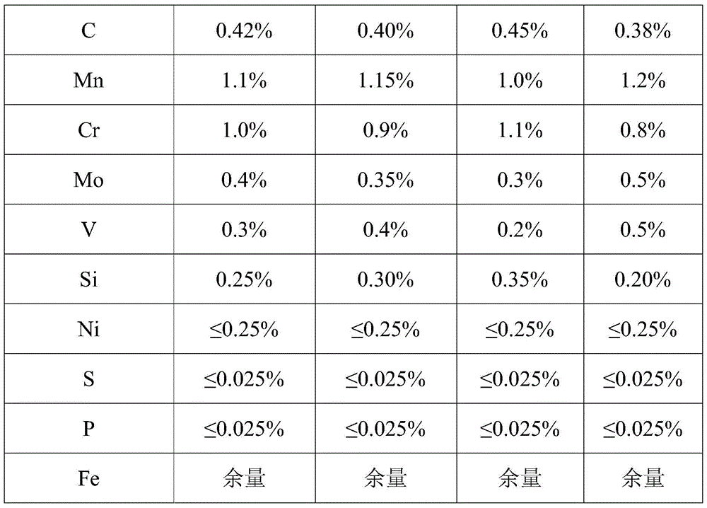
[0038] Weigh the raw materials according to the composition and mass percentage of the wear-resistant pin described in Example 1 in Table 1, crush and refine the raw materials into metal powders, and carry out pre-annealing treatment at 760°C under hydrogen or vacuum conditions, annealing treatment The temperature is 770°C, the annealing treatment time is 4.5 hours, the oil is cooled to 500°C and air-cooled, and the small particle powder is made into large particles or pellets after blending;
[0039] Put the above-prepared large particles or aggregate powder into the mold cavity, and roll it into a pin blank under a pressure of 500MPa;
[0040] Quenching the above-prepared pin blank with quenching oil at 850°C, heat preservation for 2 hours, oil cooling to room temperature, then tempering at 520°C, heat preservation for 2 hours; air cooling to obtain the crude pin;
[0041] After the crude product of the above-mentioned pin shaft is rough-turned and finished-turned on the lat...
Embodiment 2
[0044] Weigh the raw materials according to the composition and mass percentage of the wear-resistant pin described in Example 2 in Table 1, crush and refine the raw materials into metal powder, and carry out pre-annealing treatment at 770°C under hydrogen or vacuum conditions, annealing treatment The temperature is 765°C, the annealing treatment time is 4.5 hours, the oil is cooled to 480°C and air-cooled, and the small particle powder is made into large particles or pellets after blending;
[0045] Put the large particle or aggregate powder obtained above into the mold cavity, and roll it into a pin blank under a pressure of 510MPa;
[0046] Quenching the above-prepared pin blank with quenching oil at 855°C, heat preservation for 2 hours, oil cooling to room temperature, then tempering at 510°C, heat preservation for 2 hours; air cooling to obtain the crude pin;
[0047] After the crude product of the above-mentioned pin shaft is rough-turned and finished-turned on the lathe...
Embodiment 3
[0050] Weigh the raw material according to the composition and mass percentage of the wear-resistant pin described in Example 3 in Table 1, crush and refine the raw material into metal powder, and carry out pre-annealing treatment at 750 ° C under hydrogen or vacuum conditions, annealing treatment The temperature is 780°C, the annealing treatment time is 4 hours, the oil is cooled to 550°C and air-cooled, and the small particle powder is made into large particles or pellets after blending;
[0051] Put the large particle or aggregate powder prepared above into the mold cavity, and roll it into a pin blank under a pressure of 480MPa;
[0052] Quenching the pin blank prepared above with quenching oil at 840°C, heat preservation for 3 hours, oil cooling to room temperature, then tempering at 500°C, heat preservation for 3 hours; air cooling to obtain the crude pin;
[0053] After the crude product of the above-mentioned pin shaft is rough-turned and finished-turned on the lathe, ...
PUM
 Abstract
Description
Claims
Application Information