Al technical title is built by PatSnap Al team. It summarizes the technical point description of the patent document.
A flexible support and support rod technology, used in positioning devices, clamping devices, supports, etc., can solve the problems of low machining accuracy and low positioning accuracy of complex thin-walled blade parts, and achieve high-speed and high-efficiency machining accuracy and machining quality. , Accurate support force, the effect of improving stiffness
Active Publication Date: 2016-10-26
NORTHWESTERN POLYTECHNICAL UNIV
View PDF5 Cites 0 Cited by
Summary
Abstract
Description
Claims
Application Information
AI Technical Summary
This helps you quickly interpret patents by identifying the three key elements:
Problems solved by technology
Method used
Benefits of technology
Problems solved by technology
[0006] In order to overcome the disadvantages of the existing support device due to the low positioning accuracy and the low machining accuracy of complex thin-walled blade parts, the present invention provides a flexible support device
Method used
Image
Click on the blue label to locate the original text in one second.
Reading with bidirectional positioning of images and text.
Examples
Embodiment Construction
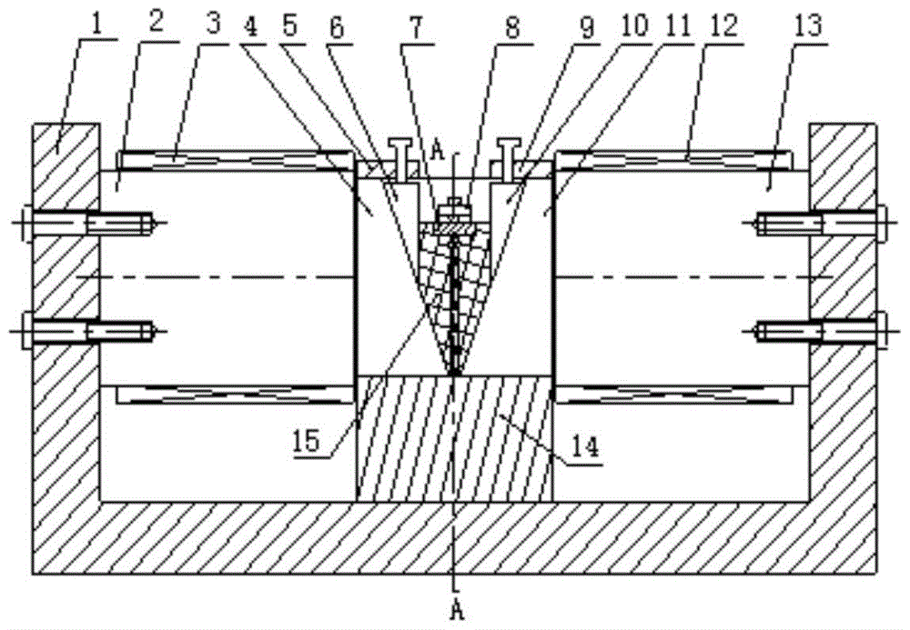
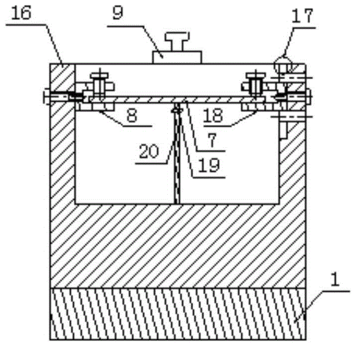
[0015] The following examples refer to Figure 2-4 .
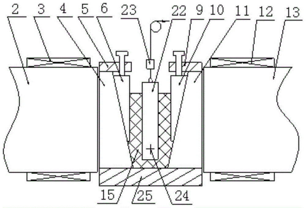
[0016] The flexible supporting device of the present invention comprises a left iron core 2, a left excitation coil 3, a left wedge-shaped guide container wall 4, a left support plate 5, a left wedge-shaped block 6, a right support plate 9, a right wedge-shaped block 10, a right wedge-shaped guide container wall 11, The right excitation coil 12, the right iron core 13 and the magnetorheological fluid 15 also include a frame 1, a left initial positioning device 8, a right initial positioning device 18, a displacement sensor 19, a support rod 20 and a DC stabilized voltage power supply 21.
[0017] Frame 1 is a U-shaped structure made of No. 45 steel, with a size of 500×200×250mm; the left wedge-shaped guide container wall 4 and the right wedge-shaped guide container wall 11 are made of No. 45 steel materials, and the left wedge-shaped guide container wall 4 and The inner side of the right wedge-shaped guide container wall ...
PUM
Abstract
The invention discloses a flexible supporting device which is used for solving the technical problem that as an existing supporting device is low in positioning accuracy, the part machining accuracy is low. According to the technical scheme, the flexible supporting device comprises a left iron core, a left magnet exciting coil, a left wedge-shaped guide container wall, a left supporting plate, a left wedge-shaped block, a right supporting plate, a right wedge-shaped block, a right wedge-shaped guide container wall, a right magnet exciting coil, a right iron core and magnetorheological fluid, and further comprises a machine frame, a left primary positioning device, a right primary positioning device, a displacement sensor, a supporting rod and a direct current voltage stabilizing power source; blades are fixed to the left primary positioning device and the right primary positioning device through a bolt, and the left primary positioning device and the right primary positioning device are fixed to the container walls parallel to the direction of a magnetic field through bolts. The blades are immersed in the magnetorheological fluid, receding deformation, caused by insufficient rigidity of the blades, of the blades in the cutting process is avoided, the positioning accuracy of a complex thin wall part is improved, the rigidity of the complex thin wall part is accordingly improved, and the high-speed and efficient machining accuracy and the machining quality of the complex thin wall part are guaranteed.
Description
technical field [0001] The invention relates to a supporting device, in particular to a flexible supporting device. Background technique [0002] In the machining process, traditional fixtures are mainly purely mechanical fixtures. This kind of fixture has a single structure, is inconvenient to disassemble and assemble, and has a low degree of automation. For thin-walled workpieces with complex shapes and structures, it cannot overcome the low rigidity and easy deformation of the workpiece. And other problems, the positioning and dimensional accuracy of the workpiece after tightening cannot be guaranteed. At the same time, for workpieces with irregular geometric shapes, positioning and tightening cannot be performed. [0003] In order to solve these problems, avoid the disadvantages of low melting point alloys such as lead, antimony, bismuth, tin, etc. that have environmental pollution, and use the phase change fixture designed for the liquid-solid two-phase transition chara...
Claims
Application Information
Patent Timeline
Application Date:The date an application was filed.
Publication Date:The date a patent or application was officially published.
First Publication Date:The earliest publication date of a patent with the same application number.
Issue Date:Publication date of the patent grant document.
PCT Entry Date:The Entry date of PCT National Phase.
Estimated Expiry Date:The statutory expiry date of a patent right according to the Patent Law, and it is the longest term of protection that the patent right can achieve without the termination of the patent right due to other reasons(Term extension factor has been taken into account ).
Invalid Date:Actual expiry date is based on effective date or publication date of legal transaction data of invalid patent.