Efficient rebar derusting device

A steel bar and high-efficiency technology, applied in the field of high-efficiency steel bar rust removal devices, can solve the problems of decreased durability, unguaranteed engineering quality, and high cost of rust removal by a rust remover, so as to reduce work difficulty, reduce labor costs, and remove rust. good effect

Inactive Publication Date: 2015-05-20
JIANGSU JINMAO CONSTR GRP
View PDF0 Cites 5 Cited by
  • Summary
  • Abstract
  • Description
  • Claims
  • Application Information

AI Technical Summary

Problems solved by technology

"In order to strictly control the construction and building life and quality, rust removal of steel bars is an essential process. In the natural environment, when the surface of steel bars comes into contact with water and air, a layer of iron oxide will form on the surface, which is rust. Rusty steel bars cannot bond well with concrete, which affects the joint work of steel bars and concrete. If the scale is not cleaned, it will continue to develop, resulting in damage to the concrete and a reduction in the bearing capacity of reinforced concrete structural members. Finally, the concrete Decreased structural durability. Structural components are completely destroyed, and the quality of the project cannot be guaranteed. There are many ways to remove rust from steel bars. The commonly used methods are manual rust removal, rust removal by rust remover, and chemical method. Large size, low efficiency, high rust removal cost of rust remover, chemical rust removal is harmful to human body, so a simple and efficient rust removal device is needed

Method used


Image

  • Efficient rebar derusting device
  • Efficient rebar derusting device

Examples


Embodiment Construction

[0014] The present invention will be further explained below in conjunction with the accompanying drawings and specific embodiments. It should be understood that the following specific embodiments are only used to illustrate the present invention and are not intended to limit the scope of the present invention. It should be noted that the words "front", "rear", "left", "right", "upper" and "lower" used in the following description refer to the directions in the drawings, and the words "inner" and "outer ” refer to directions towards or away from the geometric center of a particular part, respectively.

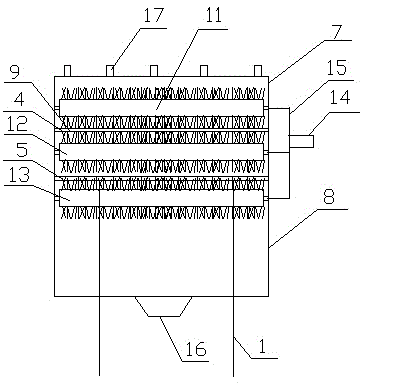
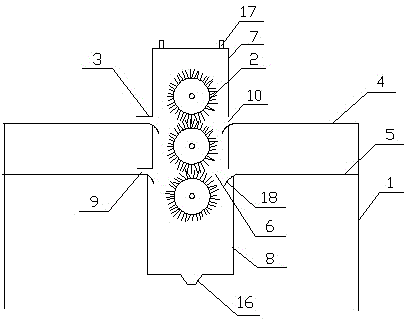
[0015] As shown in the figure, a high-efficiency steel bar rust removal device according to the present invention includes a workbench 1, a wire roller 2, and a limit plate 3. The workbench 1 has two layers, and the two layers of the workbench are in the middle of planes 4 and 5. A long hole 6 is provided, and the long hole 6 is provided with dust covers 7 and 8 up and down, an...


PUM


Abstract

The invention discloses an efficient rebar derusting device which comprises a working table, iron wire rollers and a limiting plate. The working table is provided with two layers, a long hole is formed between the planes of the two layers of the working table, dust covers are arranged on the upper portion and the lower portion of the long hole, the front end faces and the rear end faces of the dust covers are provided with two inlets and outlets, and three iron wire rollers are arranged in the dust covers. The first iron wire roller is arranged above the upper layer plane of the working table, the second iron wire roller is arranged between the two layers of planes of the working table, the third iron wire roller is arranged below the lower layer plane of the working table, and iron wires on the sides of the three iron wire rollers are in contact with each other. The side of the upper dust cover is provided with a motor and a transmission device, the transmission device is connected with the three iron wire rollers, the bottom of the lower dust cover is provided with a discharging port, and the limiting plate is horizontally placed above the inlets. The efficient rebar derusting device is simple to manufacture and low in cost; the double-layer working table performs derusting simultaneously; a limiting device causes rebars to enter orderly, the working efficiency is high, the derusting effect is good, the derusting labor cost is reduced, and the working difficulty is reduced.

Description

technical field [0001] The invention belongs to the field of construction machinery processing, and in particular relates to a high-efficiency steel bar derusting device. Background technique [0002] In 5.2.4 of the "Code for Construction Quality Acceptance of Concrete Structure Engineering" GB50204-2002 stipulates: "The steel bar should be straight and free of damage, and the surface should not have cracks, oil stains, granular or flaky old rust." For strict construction and Building life and quality, rust removal of steel bars is an essential process. In the natural environment, when the surface of steel bars comes into contact with water and air, a layer of iron oxide will form on the surface. This is rust. Rusted steel bars cannot It is well bonded to concrete, which affects the joint work of steel bars and concrete. If the scale is not cleaned, it will continue to develop, resulting in damage to the concrete and a reduction in the bearing capacity of reinforced con...

Claims


Application Information

Patent Timeline
Patent Type & Authority Applications(China)
IPC IPC(8): B24B27/033B24B55/06
CPCB24B27/033B24B55/06
Inventor 胡友华胡友林宋文友袁荣荣陈卫华
Owner JIANGSU JINMAO CONSTR GRP
Why Eureka
Try Eureka