
Laser heterodyne interference linearity measuring device and laser heterodyne interference linearity measuring method with six-degree-of-freedom detection

A technology of laser heterodyne interference and measuring device, which is applied in the direction of measuring device, optical device, instrument, etc.

Active Publication Date: 2015-05-20
ZHEJIANG SCI-TECH UNIV
View PDF5 Cites 52 Cited by
  • Summary
  • Abstract
  • Description
  • Claims
  • Application Information

AI Technical Summary

Problems solved by technology

The principle of laser heterodyne interference and laser spot detection is adopted, which not only realizes the simultaneous detection of multiple degrees of freedom motion parameters of the measured object, but also realizes error compensation for straightness and position detection, and solves the problem of laser heterodyne interference. The technical problem of the influence of the rotation error on the measurement result in the straightness measurement has improved the measurement accuracy of the straightness and its position detection, and realized the simultaneous measurement of the error parameters of the six degrees of freedom of the measured object

Method used


Image

  • Laser heterodyne interference linearity measuring device and laser heterodyne interference linearity measuring method with six-degree-of-freedom detection
  • Laser heterodyne interference linearity measuring device and laser heterodyne interference linearity measuring method with six-degree-of-freedom detection
  • Laser heterodyne interference linearity measuring device and laser heterodyne interference linearity measuring method with six-degree-of-freedom detection

Examples


Embodiment Construction

[0061] The present invention will be further described below in conjunction with drawings and embodiments.

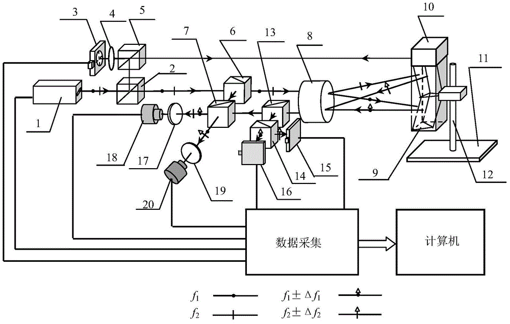
[0062] The optical path structure of the device of the present invention is as figure 1 As shown, including laser heterodyne interference straightness and its position detection part and error detection and compensation part, the specific implementation process is as follows:

[0063] Dual-frequency laser 1 adopts a He-Ne frequency-stabilized laser with transverse Zeeman effect, and the output frequencies are f 1 and f 2 The orthogonal linearly polarized light beam is divided into two beams of light after the first ordinary beam splitter 2, wherein the reflected beam is incident on the plane reflector installed on the top of the reflective prism 9 formed by the upper and lower rectangular prisms after being reflected by the second ordinary beam splitter 5 10, the plane mirror 10 and the reflective prism 9 form a measuring mirror, which is fixed on the mobile platform ...


PUM


Abstract

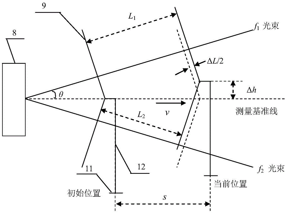
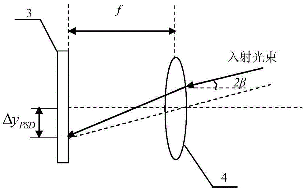
The invention discloses a laser heterodyne interference linearity measuring device and a laser heterodyne interference linearity measuring method with six-degree-of-freedom detection. The laser heterodyne interference linearity measuring device comprises a laser heterodyne interference linearity and position detection part and an error detection and compensation part; a four-degree-of-freedom error detection light path consisting of three ordinary beam splitters, a polarizing beam splitter, a plane reflecting mirror, a convex lens, a position sensitive detector and two four-quadrant detectors is additionally arranged in a light path structure of the laser heterodyne interference linearity and position detection part. By utilizing a method for integrating the laser heterodyne interferometry and a laser spot detection method, the simultaneous six-degree-of-freedom detection of a deflection angle, a pitch angle, a rolling angle, horizontal linearity, vertical linearity and linearity position of a measured object can be realized, the error compensation is carried out for the vertical linearity and the vertical linearity position, the influence of rotation error of the measured object on a measurement result in the linearity measuring process can be eliminated, and the measurement precision of the laser heterodyne interference linearity and the position of the laser heterodyne interference linearity can be improved.

Description

technical field [0001] The invention relates to a laser heterodyne interference straightness measurement device and method, in particular to a laser heterodyne interference straightness measurement device and method with six-degree-of-freedom detection. Background technique [0002] In the manufacture of modern precision machinery and instruments, straightness, as one of the main geometric elements that characterize the shape of workbench or guide rail parts, plays an important role in the detection of mechanical accuracy. At present, there are many straightness measurement methods. According to whether laser is used as the measurement carrier, it can be divided into laser measurement method and non-laser measurement method. Compared with the latter, the former can achieve higher measurement accuracy and convenient measurement. The main object of academic and business research. Among the laser measurement methods, the laser heterodyne straightness interferometer has been wi...

Claims


Application Information

Patent Timeline
IPC IPC(8): G01B11/27G01B11/00
Inventor 陈本永严利平张恩政徐斌
Owner ZHEJIANG SCI-TECH UNIV
Learn More