Membrane material-based micro-fluidic chip

A microfluidic chip and membrane material technology, applied in the direction of analysis materials, material inspection products, fluid controllers, etc., can solve the problem that there is no way to integrate chip precision level structure, lateral chromatography technology has no control means, and lateral layers are limited Analysis of technical precision and accuracy and other issues, to achieve the effect of simple design, fast detection, and convenient storage

Inactive Publication Date: 2016-08-17
张鹏
View PDF8 Cites 17 Cited by
  • Summary
  • Abstract
  • Description
  • Claims
  • Application Information

AI Technical Summary

Problems solved by technology

However, there is no better control method for lateral chromatography technology, and there is no way to integrate chip precision level structure, which limits the improvement of precision and accuracy of lateral chromatography technology

Method used


Image

  • Membrane material-based micro-fluidic chip
  • Membrane material-based micro-fluidic chip
  • Membrane material-based micro-fluidic chip

Examples


Embodiment 1

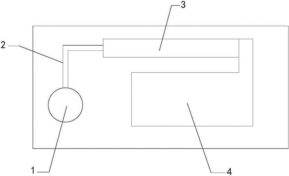
[0035] see figure 1 , a microfluidic chip based on a membrane material in a preferred embodiment of the present invention includes a sample port 1, a fluid channel 2, a detection area 3 and a liquid collection area 4 that are connected to each other in sequence, wherein the fluid channel 2 is used to The sample added by the sample injection port is transported to the detection area under capillary action. The detection membrane for lateral flow detection of the sample is provided in the detection area 3, and the collection device for absorbing excess samples is provided in the liquid collection area 4. One end of the membrane is connected to the fluid channel and the other end is connected to the collection device. It should be noted that the main difference between the microfluidic chip based on the membrane material of the present invention and the prior art is that the microfluidic technology is used to make the sample liquid flow autonomously under capillary action, and no...

Embodiment 2

[0048] The present invention provides a method for preparing the aforementioned microfluidic chip based on membrane materials, comprising the following steps:

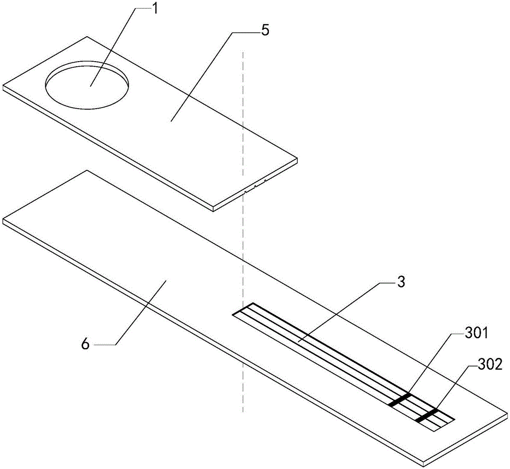
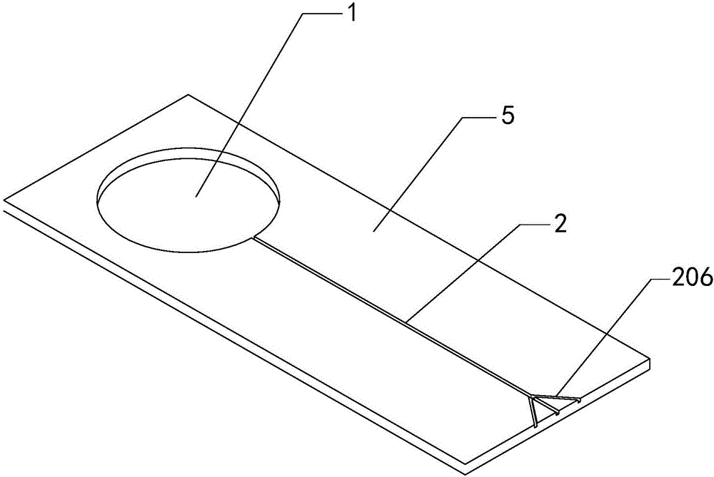
[0049] S1. Chip preparation: process the upper chip and the lower chip into such Figure 1 to Figure 10 the structure shown;

[0050] S2. Detection membrane preparation: pour the membrane material raw material into the detection area, remove excess volatile components after shaping, and form a detection membrane;

[0051] S3. Flow channel processing: Design the part of the flow channel that needs to be burned and removed on the software, use laser to process the flow channel on the detection film according to the design, and form multiple detection diaphragms;

[0052] S4. Probe preparation: Coupling the antibody required in the lateral flow detection process to the fluorescent protein;

[0053] S5. Preparation of immune reagents: respectively coat the required antibodies or antigens on the detection line and control...

Embodiment 3

[0061] The present invention provides a method for using the membrane material-based microfluidic chip described in Embodiment 1. In this example, the myoglobin monoclonal antibody prepared by conventional monoclonal antibody technology was used to immobilize myoglobin antibody and rabbit IgG in the rear region of the detection membrane to form a detection line and a control line. Erythroprotein monoclonal antibody and goat anti-rabbit IgG are coupled with fluorescent microspheres (diameter 200nm) as a probe solution, and then the myoglobin antigen in the sample is detected by the double-antibody sandwich method, and the myoglobin in the liquid sample to be tested is detected protein content.

[0062] Specific steps are as follows:

[0063] S1. Probe preparation

[0064] 1) Take 500 μl of fluorescent latex particle solution (containing carboxyl groups) with an emission wavelength of 550nm to 700nm, wash with pH6.0 MES buffer and centrifuge three times, then dilute the precip...


PUM


Abstract

The present invention relates to a microfluidic chip, in particular to a microfluidic chip based on a membrane material; it includes a sample inlet, a fluid channel, a detection area, and a liquid collection area that are connected to each other in sequence, wherein the fluid channel is used to automatically The sample added by the sample port is transported to the detection area under capillary action. The detection area is equipped with a detection membrane for lateral chromatography detection of the sample, and the liquid collection area is equipped with a collection device for absorbing excess samples. The detection membrane One end is connected to the fluid channel, and the other end is connected to the collection device; the microfluidic chip based on the membrane material of the present invention can effectively improve the precision and accuracy of the lateral flow chromatography technique.

Description

technical field [0001] The invention relates to a microfluidic chip, in particular to a microfluidic chip based on a membrane material. Background technique [0002] Microfluidic chip, also known as Lab-on-a-Chip (Lab-on-a-Chip), is a micro-total analysis system (μ-TAS), which is a system that manipulates the flow of a small volume of fluid in a small channel or component. , involving many basic disciplines such as physics, chemistry, and biology. Based on microfluidic technology, it prepares small-scale (from micron to nanometer) channels, chambers, valves, pumps and other devices, and uses various physical methods to study the specific properties of small-scale devices and develop small-scale control fluids. Movement and physicochemical changes. The main driving force of the existing microfluidic chip technology is pressure drive, electroosmotic drive, centrifugal drive, etc., which need to use external force to control the material in the chip, and cannot realize autono...

Claims


Application Information

Patent Timeline
Patent Type & Authority Applications(China)
IPC IPC(8): G01N33/558G01N33/577G01N33/68G01N21/64B01L3/00
CPCG01N33/558B01L3/5027B01L3/502761B01L2200/10B01L2300/0861B01L2300/0887B01L2300/12B01L2400/0406G01N21/6486G01N33/577G01N33/68
Inventor 张鹏徐兢廖平璋
Owner 张鹏
Why Eureka
Try Eureka