Optical frequency domain reflectometer with optical wave frequency shift modulation

A technology of optical frequency domain reflectometer and frequency shift modulation, which is applied in the directions of processing polarization reflectometer, detecting backscattered light in the frequency domain, testing optical fiber/optical waveguide equipment, etc., which can solve the mutual interference of interference signals and other problems, to achieve the effect of suppressing mutual interference, reducing the impact, and increasing the frequency of the interference signal

Active Publication Date: 2017-12-26
BEIJING INST OF AEROSPACE CONTROL DEVICES
View PDF6 Cites 17 Cited by
  • Summary
  • Abstract
  • Description
  • Claims
  • Application Information

AI Technical Summary

Problems solved by technology

[0008] The technical problem solved by the present invention is: for the existing optical frequency domain reflectometer, there is a problem of mutual interference between the interference signals of scattered signal light symmetrical to zero time delay; an optical frequency reflectometer with optical frequency shift modulation is proposed, through Optical wave frequency shift modulation suppresses mutual interference between interference signals of scattered signal light with respect to zero-delay symmetry, reduces the difficulty of optical path adjustment, and increases the maximum measurement fiber length at the same time

Method used


Image

  • Optical frequency domain reflectometer with optical wave frequency shift modulation
  • Optical frequency domain reflectometer with optical wave frequency shift modulation
  • Optical frequency domain reflectometer with optical wave frequency shift modulation

Examples


Embodiment Construction

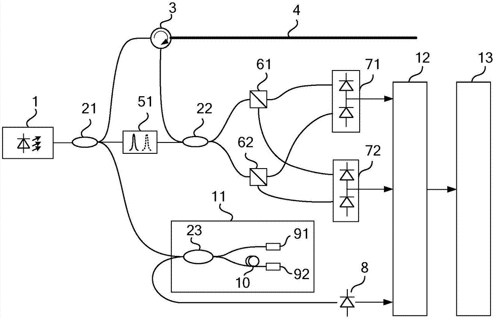
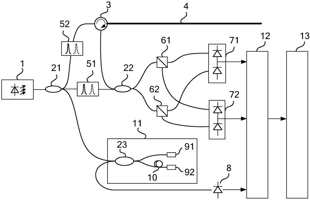
[0024] The present invention discloses an optical frequency domain reflectometer for light wave frequency shift modulation, such as figure 1 As shown, the optical frequency domain reflectometer for optical wave frequency shift modulation includes a narrow linewidth scanning laser 1, a first optical fiber coupler 21, an optical circulator 3, a first optical wave frequency shifter 51, a second optical fiber coupler 22, a first Polarizing beam splitter 61, second polarizing beam splitter 62, first balanced photodetector 71, second balanced photodetector 72, third fiber coupler 23, first Faraday rotating mirror 91, second Faraday rotating reflector Mirror 92, time-delay optical fiber 10, photodetector 8, analog-to-digital converter 12, signal processing unit 13;

[0025]The output light of the narrow-linewidth scanning laser 1 is divided into three paths after passing through the first fiber coupler 21; the first path of light output by the first fiber coupler 21 is input to be te...


PUM


Abstract

The invention discloses an optical frequency domain reflectometer with optical wave frequency shift modulation, which comprises a narrow linewidth scanning laser, a first optical fiber coupler, an optical circulator, a to-be-measured optical fiber, an optical wave frequency shifter, a second optical fiber coupler, a first polarization beam splitter, a second polarization beam splitter, a first balanced photodetector, a second balanced photodetector, a third optical fiber coupler, a first Faraday rotating mirror, a second Faraday rotating mirror, a reference optical fiber interferometer, a photodetector and a signal acquisition and processing unit. Through frequency shift modulation on measurement light and reference light, interference signals produced by superposition of scattering signal light of the to-be-measured optical fiber which is symmetrical about zero delay and local oscillation light are separated on the spectrum. According to the optical frequency domain reflectometer with optical wave frequency shift modulation, mutual interference among the interference signals of the to-be-measured optical fiber scattering signal light which is symmetrical about zero delay can be suppressed, measurement of the scattering signal light which is symmetrical about zero delay can be realized, and the maximum optical fiber measurement length can be improved.

Description

technical field [0001] The invention relates to an optical frequency domain reflectometer, in particular to an optical frequency domain reflectometer with light wave frequency shift modulation. Background technique [0002] Optical frequency domain reflectometer is an important means of optical fiber sensing measurement and optical fiber device measurement; through optical frequency domain reflectometer to measure the backward Rayleigh scattering along the optical fiber and the backward reflection of the fiber grating, the temperature, strain, vibration, etc. of the optical fiber can be realized. Distributed measurement or multi-point measurement; through optical frequency domain reflectometer to measure the Rayleigh scattering of optical fiber and the back reflection of optical device, it can realize the measurement of various parameters such as loss, dispersion and polarization of optical fiber and optical device . [0003] For optical fiber sensing measurement applicatio...

Claims


Application Information

Patent Timeline
Patent Type & Authority Applications(China)
IPC IPC(8): G01D5/353G01M11/02
CPCG01D5/35303G01D5/35306G01D5/35367G01M11/00G01M11/3172G01M11/3181
Inventor 唐才杰王学锋江淮蓝天罗明明卞贺明崔留住李保勇
Owner BEIJING INST OF AEROSPACE CONTROL DEVICES
Why Eureka
Try Eureka