
Coordinative optimization control method based on AGC and AVC

A control method and coordinated optimization technology, applied in AC network voltage adjustment, load forecasting in AC network, reactive power adjustment/elimination/compensation, etc., can solve the problem of affecting grid economy and power quality, without considering active frequency The adjustment of reactive power and voltage interacts with each other, reducing the working efficiency of the control device, etc.

Inactive Publication Date: 2015-05-20
STATE GRID CORP OF CHINA +2
View PDF3 Cites 8 Cited by
  • Summary
  • Abstract
  • Description
  • Claims
  • Application Information

AI Technical Summary

Problems solved by technology

In the power grid, there is a weak coupling relationship between active power and reactive power. At present, the control of AGC and AVC is mostly designed based on the decoupling of active power and reactive power. They adjust the frequency and voltage of the power grid respectively, without taking into account Interaction between regulation of active frequency and regulation of reactive voltage
The adjustment of AGC affects the control effect of AVC, thus causing the adjustment of AVC; and the adjustment of AVC will affect the control effect of AGC, which in turn causes the adjustment of AGC
This causes the reciprocating adjustment of AGC and AVC, which not only reduces the working efficiency of the control device, but also affects the normal operation of the power grid.
The lack of coordination between AGC and AVC will cause adverse effects on the safety and stability of the power grid, and affect the economy and power quality of the power grid

Method used


Image

  • Coordinative optimization control method based on AGC and AVC
  • Coordinative optimization control method based on AGC and AVC
  • Coordinative optimization control method based on AGC and AVC

Examples


Embodiment Construction

[0052] The present invention will be further described below in conjunction with the accompanying drawings and embodiments.

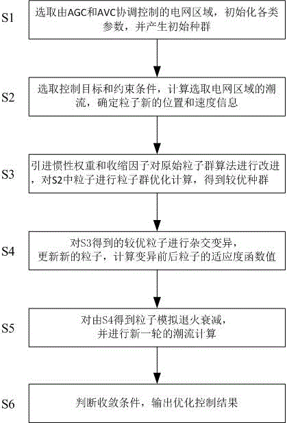
[0053] Such as figure 1 Shown, the present invention comprises the steps:

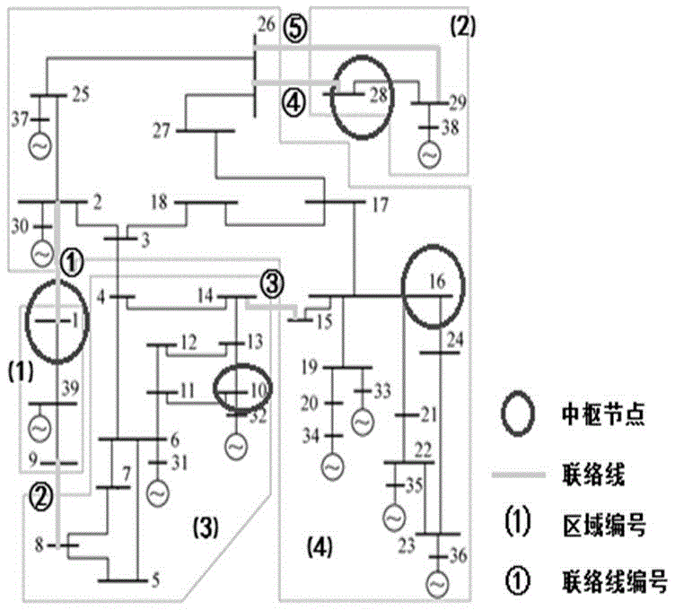
[0054] Step 1. The selected power grid area has AGC and AVC functions. The basic parameters of the given point include the active output of each generator in the area, the reactive output of each generator, the voltage of the central node, and the power of the inter-regional tie line. Various parameters of the initialized particles include the population Scale, maximum number of evolutions, learning factor value.

[0055] Such as figure 2As shown, the basic parameters of the power grid here select the New England 10-generator 39-node system, given the active power, reactive power ratings and rated voltages of each unit, and the generators in the system all participate in the output adjustment, and also participate in the machine terminal. voltage adjustment. Initialize part...


PUM


Abstract

The invention discloses a coordinative optimization control method based on AGC and AVC. The method includes: selecting a power grid area controlled by AGC and AVC in a coordinative manner, setting power grid basic parameters, and initiating various particle parameters to produce an initial swarm; selecting a control target and constraint conditions, calculating the tidal currents of the selected power grid area, and determining the new positions and speed information of particles; introducing inertia weight and contraction factors to improve an initial particle swarm algorithm, performing particle swarm optimization calculation on the particles in the second step to obtain the optimized swarm; performing hybrid mutation on the optimized particles obtained in the third step, updating the new particles, and calculating the fitness function values of the particles before and after the mutation; performing simulated annealing attenuation on the particles obtained in the fourth step, and performing a new round of tidal current calculation; judging convergence conditions, and outputting optimization control results. The method has the advantages that the problems of AGC and AVC coordinative optimization control are solved, system tidal currents are optimized, and power grid frequency and voltage quality are improved.

Description

technical field [0001] The invention relates to a coordinated optimization control method based on AGC and AVC. Background technique [0002] At present, my country's power grid mainly uses automatic generation control (AGC) and automatic voltage control (AVC) to adjust the active power and reactive power of the power grid respectively to maintain the stability of frequency and voltage. In the power grid, there is a weak coupling relationship between active power and reactive power. At present, the control of AGC and AVC is mostly designed based on the decoupling of active power and reactive power. They adjust the frequency and voltage of the power grid respectively, without taking into account Interaction between regulation of active frequency and regulation of reactive voltage. The adjustment of AGC affects the control effect of AVC, thus causing the adjustment of AVC; and the adjustment of AVC will affect the control effect of AGC, thus causing the adjustment of AGC. Th...

Claims


Application Information

Patent Timeline
Patent Type & Authority Applications(China)
IPC IPC(8): H02J3/00H02J3/16H02J3/18G06Q10/04G06Q50/06
CPCG06Q10/04G06Q50/06H02J3/003H02J3/46Y02E40/30Y02E40/70Y04S10/50
Inventor 陈浩钱军胡斌奇胡伟
Owner STATE GRID CORP OF CHINA
Learn More