Integrated radioactive source welding chamber

A technology of radioactive source and welding chamber, applied in the field of integrated radioactive source welding chamber, can solve the problems of increased manufacturing cost, lack of installation and positioning, welding quality influence, etc., to achieve improved position accuracy and installation and positioning accuracy, simple and practical structure, rotating high precision effect

Inactive Publication Date: 2015-05-27
SHANGHAI UNIV
View PDF5 Cites 3 Cited by
  • Summary
  • Abstract
  • Description
  • Claims
  • Application Information

AI Technical Summary

Problems solved by technology

[0002] There are some problems when the existing welding machine is working: First, the welding chamber is not integrally formed, and the accumulation of manufacturing errors in each part reduces the overall size and position accuracy of the welding chamber, which exceeds the specified range, which forces the selection of higher manufacturing accuracy to Reduce the manufacturing error, but this will greatly increase the manufacturing cost; at the same time, the assembly and disassembly of the non-integrated welding chamber is more complicated, and the installation error is relatively large due to the lack of installation positioning
The above reasons lead to an increase in the coaxiality error between the rolling bearing and the gear on the left side of the welding chamber, the large runout of the nuclear fuel pipe circle, and the large change in the distance between the welding seam and the tungsten electrode of the welding torch, which seriously reduces the welding quality.
Secondly, as the welding progresses, the debris generated during the welding process will increase on the inner wall of the welding chamber, which will have a certain impact on the welding quality. Therefore, the inner wall of the welding chamber needs to be cleaned regularly, and the original structure is not conducive to cleaning

Method used


Image

  • Integrated radioactive source welding chamber
  • Integrated radioactive source welding chamber
  • Integrated radioactive source welding chamber

Examples


Embodiment Construction

[0021] Embodiments of the present invention are described in detail as follows in conjunction with accompanying drawings:

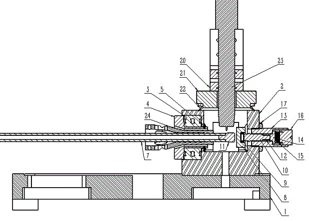
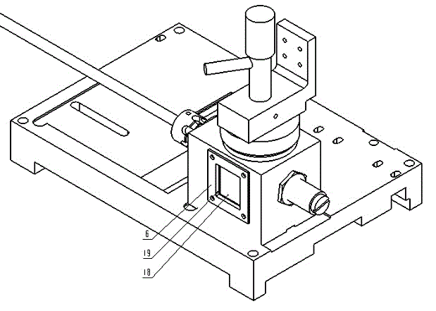
[0022] like Figure 1 to Figure 8 As shown, an integrated radioactive source welding chamber includes an installation base plate 1, a welding chamber 2, an observation window assembly, a clamping guide assembly, a welding torch installation sealing assembly, and a heat dissipation double spring top plate assembly. The welding chamber 2 and the installation base plate 1 Fixed connection, the heat dissipation double spring top plate assembly is installed on the right end of the welding chamber 2, the welding torch installation sealing assembly is installed on the top of the welding chamber 2, the clamping guide assembly is installed on the left end of the welding chamber 2, and the welding chamber 2 The front and rear ends are provided with observation window components.

[0023] The heat dissipation double spring top plate assembly includes a heat dissipa...


PUM


Abstract

The invention relates to an integrated radioactive source welding chamber which comprises a mounting bottom plate, a welding small chamber, view window components, a clamping guide component, a welding gun mounting and sealing component and a heat radiating double-spring top plate component, wherein the welding small chamber is fixedly connected with the mounting bottom plate; the heat radiating double-spring top plate component is mounted at the right end of the welding small chamber; the welding gun mounting and sealing component is mounted at the top of the welding small chamber; the clamping guide component is mounted at the left end of the welding small chamber; the view window components are arranged at the front and back ends of the welding small chamber. The welding small chamber of the integrated radioactive source welding chamber is integrally formed; the processing size precision, position precision and mounting position precision are greatly improved; the gas tightness of the welding chamber is enhanced; the welding small chamber is convenient to dismount and the inner wall of the welding small chamber is convenient to clean. The integrated radioactive source welding chamber disclosed by the invention is simple and practical in structure, convenient to operate, high in rotating precision during working, and stable, safe and reliable.

Description

technical field [0001] The invention relates to the field of welding machinery technology, in particular to an integrated radioactive source welding chamber installed in high-risk environments such as radioactive source heat chambers for automatic TIG welding of nuclear fuel pipe end plugs for nuclear power. Background technique [0002] There are some problems when the existing welding machine is working: First, the welding chamber is not integrally formed, and the accumulation of manufacturing errors in each part reduces the overall size and position accuracy of the welding chamber, which exceeds the specified range, which forces the selection of higher manufacturing accuracy to The manufacturing error is reduced, but this greatly increases the manufacturing cost; at the same time, the assembly and disassembly of the non-integrated welding chamber is relatively complicated, and due to the lack of installation positioning, the installation error is relatively large. The abo...

Claims


Application Information

Patent Timeline
Patent Type & Authority Applications(China)
IPC IPC(8): B23K9/32
CPCB23K9/12B23K9/167B23K9/32B23K37/0538
Inventor 邵道勇陈国祥陈方泉
Owner SHANGHAI UNIV
Why Eureka
Try Eureka