
High-precision plunger type trace sampling pump

A micro-sampling pump and plunger-type technology, applied in the direction of pumps, pump control, liquid variable capacity machinery, etc., can solve the problems of sample injection movement, high price, poor precision, etc. Smooth, structurally simple effect

Inactive Publication Date: 2015-05-27
河北雄安芯慧至上科技有限公司
View PDF7 Cites 7 Cited by
  • Summary
  • Abstract
  • Description
  • Claims
  • Application Information

AI Technical Summary

Problems solved by technology

Manual sampling has disadvantages such as low efficiency and poor precision; peristaltic sampling can easily cause sample movement, which is not suitable for micro-accurate metering; syringe pump injection can achieve accurate metering, but it is expensive

Method used


Image

  • High-precision plunger type trace sampling pump
  • High-precision plunger type trace sampling pump
  • High-precision plunger type trace sampling pump

Examples


Embodiment 1

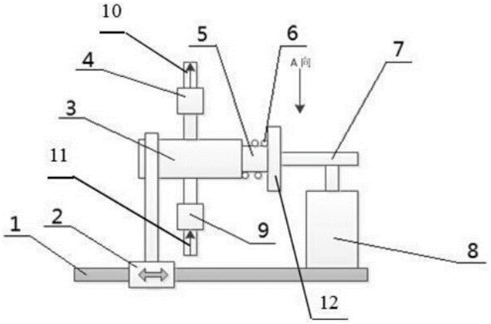
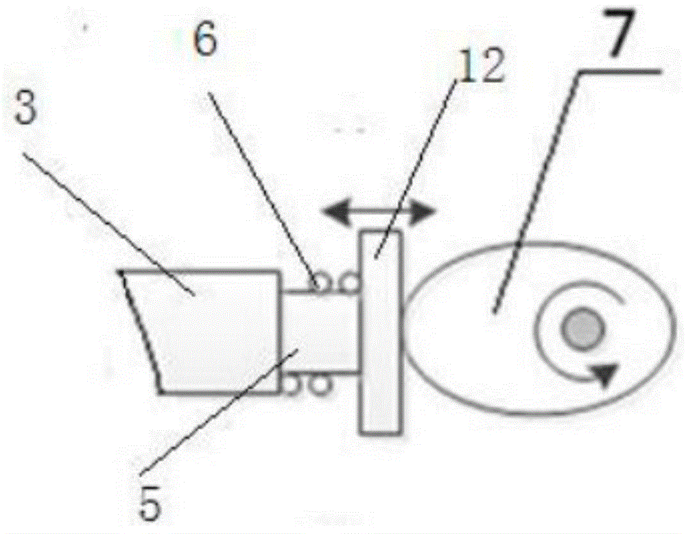
[0022] combined with figure 1 with 2 As shown, a high-precision plunger type micro-sampling pump includes: guide rails, sliding brackets, plunger pumps, liquid inlet conduits, liquid outlet conduits, liquid outlet one-way valves, liquid inlet one-way valves, springs, Cams and motors.

[0023] Described guide rail is arranged horizontally, and links to each other with the bottom end of sliding bracket, so that sliding bracket realizes moving left and right on guide rail; (not marked in the figure) are respectively provided with a liquid inlet check valve and a liquid outlet check valve, one end of the plunger of the plunger pump is embedded in the plunger pump, and the other end is provided with a clutch plate; the spring is coaxially sleeved on the plunger Above, the two ends of the spring are respectively in contact with the clutch plate and the plunger pump; the motor is fixedly placed, and a cam is fixed on the drive shaft.

[0024] Select the motor model as UTmotor35HB3...

Embodiment 2

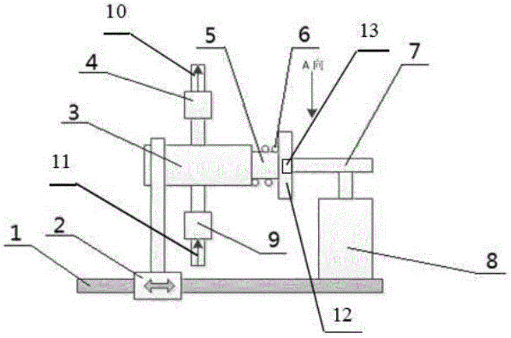
[0028] combined with image 3 with 4 As shown, a high-precision plunger type micro-sampling pump, the structure is basically the same as that of Embodiment 1, and a load cell is embedded in the clutch plate, preferably embedded in the center of the outer end surface of the clutch plate and the cam. A load cell, the load cell is connected to a controller, and the controller is connected to a motor, wherein:

[0029] The load cell is used to collect the pressure signal generated by the contact between the cam and the clutch plate when the motor drives the cam to rotate, and transmit the collected pressure signal to the controller;

[0030] The controller is used to receive the pressure signal sent by the load cell, and compare this pressure signal with the set pressure signal, when the two pressure signals are equal or the pressure signal sent by the load cell reaches the set pressure When the signal is 90-95%, send a control signal to the motor to make the motor reverse rotat...


PUM


Abstract

The invention discloses a high-precision plunger type trace sampling pump. Guide rails are horizontally arranged and are connected with the bottom end of a sliding bracket, so that the sliding bracket moves left and right on the guide rails; a plunger pump is arranged at the top end of the sliding bracket; a liquid inlet one-way valve and a liquid outlet one-way valve are respectively arranged in a liquid inlet and a liquid outlet of the plunger pump; one end of a plunger of the plunger pump is embedded inside the plunger pump; a separation-reunion plate is arranged at the other end of the plunger; a spring coaxially sleeves the plunger; two ends of the spring are respectively in contact with the separation-reunion plate and the plunger pump; a motor is fixedly placed; a cam is fixed on a driving shaft of the motor. The high-precision plunger type trace sampling pump disclosed by the invention has the advantages of simple structure, high sampling precision, adjustable trace, stable operation and low cost; the high-precision plunger type trace sampling pump is suitable for accurate sampling of an analysis instrument system and high-precision agent mixing, in particular for sampling detection of microbial culture solution.

Description

technical field [0001] The invention belongs to the technical field of liquid sampling pumps, and relates to a high-precision plunger-type micro-sampling pump, which is suitable for accurate sampling and high-precision reagent mixing of analytical instrument systems, and is especially used for microbial sampling detection. Background technique [0002] In chemical analysis, sampling precision and consistency determine the precision of measurement results. Similarly, high-precision sampling equipment is also required in the quantitative and qualitative analysis of microorganisms in liquids, and it is required that microorganisms must not be crushed during the sampling process. At present, there are mainly three methods of manual sampling, peristaltic pump sampling and syringe pump sampling in chemical analysis. Manual sampling has disadvantages such as low efficiency and poor precision; peristaltic sampling is easy to cause sample movement, which is not suitable for micro-ac...

Claims


Application Information

Patent Timeline
Patent Type & Authority Applications(China)
IPC IPC(8): F04B13/00F04B49/06G01N35/10
Inventor 卫勇常若葵郭小英吴海云刘华单慧勇
Owner 河北雄安芯慧至上科技有限公司
Learn More