Optical cable general investigation device for detecting knocking position and optical cable general investigation method for detecting knocking position

A technology for optical cables and optical fibers, which is applied in the field of optical cable survey devices for detecting knocking positions, can solve the problems that OTDR cannot extract information, achieve the effects of reducing time and management costs, and improving work efficiency

Active Publication Date: 2015-05-27
OPWILL TECH BEIJING
View PDF6 Cites 17 Cited by
  • Summary
  • Abstract
  • Description
  • Claims
  • Application Information

AI Technical Summary

Problems solved by technology

[0004] Optical cable search is a key part of the preparatory work for line engineering construction, installation and maintenance. For the detection of point-to-multipoint passive optical The central office is completed, that is, the optical time domain reflectometer (Optical Time Domain Reflectomter, hereinafter referred to as: OTDR) is used to send a test signal at the central office, the test signal is switched to the optical path under test through the optical switch, and the test signal reaches the end of the PON network (ONU ) and reflected back to the central office, the OTDR at the central office analyzes the optical path characteristics of the measured optical path by receiving the test signal returned from the original path. Extract the information of each branch from

Method used


Image

  • Optical cable general investigation device for detecting knocking position and optical cable general investigation method for detecting knocking position
  • Optical cable general investigation device for detecting knocking position and optical cable general investigation method for detecting knocking position

Examples


Embodiment 1

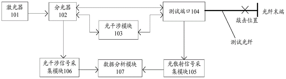
[0038] This embodiment provides an optical cable survey device for detecting the knock position, including: a laser 101, a beam splitter 102, an optical interference module 103, a light scattering signal acquisition module 105, an optical interference signal acquisition module 107, and a data analysis module 107, wherein,

[0039] The laser 101 is coupled to the beam splitter 102, and is used to generate and emit laser light to the beam splitter 102;

[0040] The beam splitter 102 is respectively coupled with the optical interference module 103, the test port and the optical interference signal acquisition module 106, and is used to receive the laser light emitted by the laser 101, divide it into two identical laser beams, and divide the first laser beam into two identical laser beams. Send to the test port, send the second laser to the optical interference module 103;

[0041] The optical interference module 103 is respectively coupled to the optical splitter 102 and the test p...

Embodiment 2

[0062] This embodiment provides an optical cable survey device for detecting the knock position, including: a laser 101, a beam splitter 102, an optical interference module 103, a light scattering signal acquisition module 105, an optical interference signal acquisition module 107, and a data analysis module 107, wherein,

[0063] The laser 101 is coupled to the beam splitter 102, and is used to generate and emit laser light to the beam splitter 102;

[0064] The beam splitter 102 is respectively coupled with the optical interference module 103, the test port and the optical interference signal acquisition module 106, and is used to receive the laser light emitted by the laser 101, divide it into two identical laser beams, and divide the first laser beam into two identical laser beams. Send to the test port, send the second laser to the optical interference module 103;

[0065] The optical interference module 103 is respectively coupled to the optical splitter 102 and the test...

Embodiment 3

[0088] This embodiment provides an application embodiment on the basis of Embodiment 1:

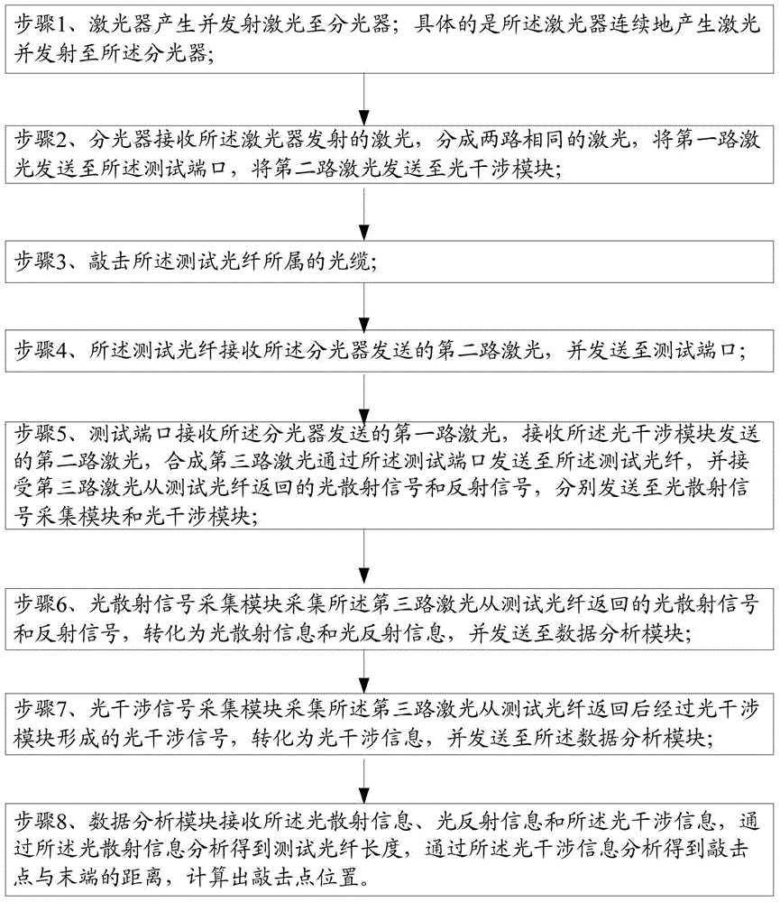
[0089] 1) The user connects the test fiber to the test port.

[0090] 2) The test instrument starts the test, that is, the laser starts to send laser light.

[0091] 3) Turn on the light scattering signal acquisition module and the optical interference signal acquisition module.

[0092] 4) The user taps the test optical cable or optical fiber.

[0093] 5) The optical interference signal acquisition module recovers the collected signal into sound and percussion waveform to determine the percussion optical cable or optical fiber. According to the collected optical interference signal, the distance between the knocking point and the end is analyzed.

[0094] 6) The light scattering signal acquisition module transmits the collected signal to the data analysis module, calculates the length of the optical fiber, and analyzes the distance between the striking point and the end according to t...


PUM


Abstract

The present application discloses an optical cable general investigation device for detecting a knocking position. The optical cable general investigation device comprises a laser device, an optical splitter, an optical interference module, an optical scattering signal acquisition module, an optical interference signal acquisition module and a data analysis module, wherein the laser device is coupled with the optical splitter; the optical splitter is respectively coupled with the optical interference module, a test port and the optical interference signal acquisition module; the optical interference module is respectively coupled with the optical splitter and the test port; the test port is respectively coupled with the optical splitter, the optical interference module and the optical scattering signal acquisition module; the optical scattering signal acquisition module is respectively coupled with the test port and the data analysis module; the optical interference signal acquisition module is respectively coupled with the optical splitter and the data analysis module; and the data analysis module is respectively coupled with the optical scattering signal acquisition module and the optical interference signal acquisition module. The optical cable general investigation device can be widely applied in the fields of cut-over, splicing, resource checking and the like.

Description

technical field [0001] The invention belongs to the field of optical cable detection, and relates to an optical cable general inspection device and method for detecting the knocking position. Background technique [0002] Testing optical fiber communications technology (optical fiber communications) stands out from traditional communication methods and has become one of the main pillars of modern communications, playing a pivotal role in modern telecommunication networks. As an emerging technology, optical fiber communication is rarely seen in the history of communication for its rapid development and wide range of applications in recent years. It is also an important symbol of the world's new technological revolution and the main transmission tool for various information in the future information society. [0003] The current demand for optical cables is increasing day by day, and the optical cables have also been expanded from the previous single core to a maximum of 2096 ...

Claims


Application Information

Patent Timeline
Patent Type & Authority Applications(China)
IPC IPC(8): G01N21/45G01V8/10
Inventor 朱天全鲍胜青赵军亮
Owner OPWILL TECH BEIJING
Why Eureka
Try Eureka