
Pulse-excitation-based optically stimulated luminescence measurement and control device

A pulse excitation, measurement and control device technology, applied in fluorescence/phosphorescence, material excitation analysis, etc., can solve the problems of loss of sample luminescence information, crosstalk, etc., and achieve the effect of adjustable light source, precise control, and simple and clear operation

Inactive Publication Date: 2015-05-27
GUANGZHOU INST OF GEOCHEMISTRY - CHINESE ACAD OF SCI
View PDF14 Cites 1 Cited by
  • Summary
  • Abstract
  • Description
  • Claims
  • Application Information

AI Technical Summary

Problems solved by technology

[0003] In the existing photoluminescence equipment, the excitation light source is mostly in the form of continuous light emission, which is likely to cause crosstalk in the overlapping part of the sample light emission and the energy of the excitation light, especially the weak light emission signal of several orders of magnitude smaller than the excitation light source.
Therefore, in the existing OSL measurement and control technology, for the detection of the weak light signal in the part of the sample OSL signal whose energy is similar to or overlaps with the energy of the excitation light, most of the avoidance measures are taken (for example, it must be based on different excitation light source and sample characteristics, the photomultiplier tube is preceded by filters with different filter characteristics), the consequence is that this measurement and control structure will inevitably lose part of the luminescence information of the sample, especially in the age of geological samples based on the optical luminescence phenomenon. In the measurement technology, optimized OSL signal selection and comprehensive OSL mechanism understanding are the basis of credible OSL-based dating technology

Method used


Image

  • Pulse-excitation-based optically stimulated luminescence measurement and control device
  • Pulse-excitation-based optically stimulated luminescence measurement and control device
  • Pulse-excitation-based optically stimulated luminescence measurement and control device

Examples


Embodiment 1

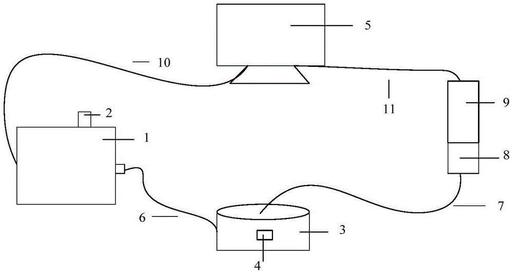
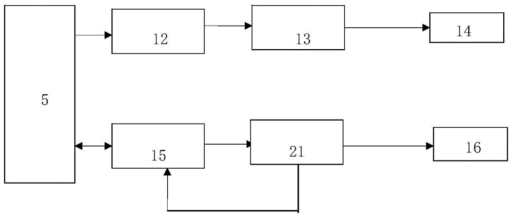
[0024] Such as figure 1 , figure 2 with image 3 As shown, the optical luminescence measurement and control device based on pulse excitation of the present embodiment includes a pulse excitation light source 1, a sample disk 3, a photomultiplier tube 9, a computer 5 (a total signal receiving control processing module), a light source control module 13, the The light outlet of the pulse excitation light source 1 is connected to the light inlet on the side of the sample disk 3 through the optical fiber 6, the light outlet on the upper part of the sample disk is connected to the photomultiplier tube 9 through the optical fiber 7, and the computer 5 (the total signal receiving control processing module) is respectively It is connected with the photomultiplier tube 9 and the light source control module 13 for signals, and a sample injection platform 4 is also provided in the sample tray, and a photomultiplier tube upper cover 8 is provided at the front end of the photomultiplier ...


PUM

PropertyMeasurementUnit
Wavelengthaaaaaaaaaa

Abstract

The invention discloses a pulse-excitation-based optically stimulated luminescence measurement and control device. The pulse-excitation-based optically stimulated luminescence measurement and control device comprises a pulse excitation optical source, a sample disc, a photomultiplier, a general signal receiving and control treatment module and an optical source control module, wherein a light outlet of the pulse excitation optical source is connected with a light inlet of the sample disc via an optical fiber; a light outlet of the sample disc is connected with the photomultiplier via an optical fiber; the general signal receiving and control treatment module is respectively connected with the photomultiplier and the optical source control module in a signal mode; the general signal receiving and control treatment module sends a signal to the optical source control module for controlling the excitation optical source, and receives the signal of the photomultiplier, and controls the photomultiplier for analyzing the received signal data. The pulse-excitation-based optically stimulated luminescence measurement and control device has the advantages of adjustable optical source, pulse light emitting, high expansibility, easiness in control, working efficiency improvement, and experiment preparation time and material waste reduction.

Description

Technical field: [0001] The invention belongs to the technical field of geological dating equipment, and relates to an optical luminescence measurement and control device based on pulse excitation. Background technique: [0002] Defects in the natural environment of crystalline solids or radiation damage caused by the influence of acquired radiation will cause defects in the crystal structure, resulting in the destruction of the charge balance in the crystal and the generation of free (energy storage) electrons. The energy-storing electrons present in the crystal will release photons when stimulated by external energy. When light energy is used for excitation, it is called photoluminescence. Photoluminescence emits phosphorescence. Under a fixed light source and the same excitation conditions, the total amount of photoluminescent light is proportional to the number of energy-storing electrons in the solid, that is, proportional to the radiation dose received by the crystal....

Claims


Application Information

Patent Timeline
IPC IPC(8): G01N21/63G01N21/64
Inventor 龚革联安琪徐红云孙卫东
Owner GUANGZHOU INST OF GEOCHEMISTRY - CHINESE ACAD OF SCI
Learn More