
Gas detection device and detection method based on smart phone and dye sensor array

A gas detection and sensing array technology, applied in the field of biomedical research and environmental monitoring, can solve the problems of difficult on-site use, complicated operation, long test time, etc., and achieve the effect of simple detection process, low price and short time consumption

Inactive Publication Date: 2017-11-28
SOUTHEAST UNIV
View PDF6 Cites 4 Cited by
  • Summary
  • Abstract
  • Description
  • Claims
  • Application Information

AI Technical Summary

Problems solved by technology

[0004] Traditional testing instruments for detecting toxic gases have not been popularized due to the characteristics of long testing time, complicated operation, and difficulty in on-site use. However, the portability and easy operability of the electronic nose can solve this problem very well.

Method used


Image

  • Gas detection device and detection method based on smart phone and dye sensor array
  • Gas detection device and detection method based on smart phone and dye sensor array
  • Gas detection device and detection method based on smart phone and dye sensor array

Examples


Embodiment 1

[0051] Color change of a thin-layer silica gel (TLC)-based sensor exposed to ethanol vapor using a smartphone-based gas detection device:

[0052] 1) Dissolve 10 mg of various porphyrin compounds and dyes such as thymol blue, methylene blue, bromocresol purple, and bromocresol green in an appropriate amount of chloroform to prepare a saturated solution. Use a capillary tube with a diameter of 0.5mm to drop the solution on the silica gel plate, and drop it into small dots with a diameter of 3mm, such as Figure 5 As shown, a 3×4 sensor array is formed. Since the boiling point of chloroform is 61.2°C, the prepared dyed silica gel plate array was baked in a constant temperature oven at 60°C for 1 hour, and the chloroform volatilized naturally, leaving various dyes on the silica gel plate.

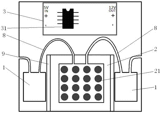
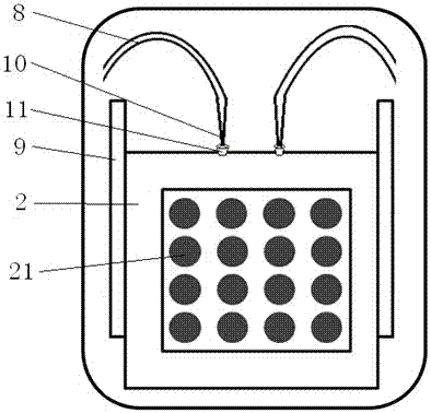
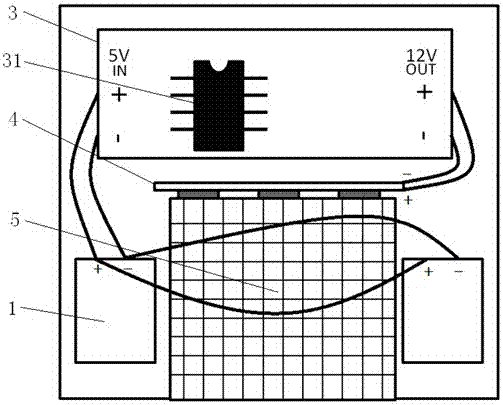
[0053] 2) Correctly install the lens 6, power supply 3, air pump 1, etc. in the supporting shell of the mobile phone, and then place the chip 2 with the dyeing array 21, and connect the air p...

Embodiment 2

[0056] Detection of the color change of a hollow TiO2 fiber-based sensor exposed to formaldehyde using a smartphone with a matching housing:

[0057] 1) Dissolve 10mg of various metalloporphyrins and dyes such as thymol blue, methylene blue, bromocresol purple, and bromocresol green in an appropriate amount of chloroform to prepare a saturated solution. Soak the TiO2 hollow fiber with a diameter of 4mm in the above solution, take it out after 3 hours, stick the fiber membrane with various dyes adsorbed on the white base to form a 3×4 sensor array.

[0058] 2) Correctly install the lens 6, power supply 3, air pump 1, etc. in the matching shell of the mobile phone, then place the chip 2 with the dyeing array 21, and connect the air inlet and outlet pipes 8 of the air pump 1 to the On the air inlet and air outlet of the chip 2 of the array 21, cover the cover of the casing.

[0059] 3) Open the app for gas detection on the mobile phone, after the first photo is displayed on the ...


PUM

PropertyMeasurementUnit
boiling pointaaaaaaaaaa

Abstract

The invention discloses a gas detection device and a gas detection method based on a smartphone and a dyeing sensing array. The gas detection device is arranged in a matched shell of the smartphone and is controlled by corresponding application software; the gas detection device comprises an air pump for providing air-sensitive reaction for gas detection, a chip, a clamping slot for insertion of the chip, a gas inlet and outlet pipeline connecting the air pump and the chip, a detection light source, a light guide plate, a lens, a camera and a power supply, wherein the air pump is electrically connected with the power supply which is electrically connected with the light source, multiple air-sensitive dyes are formed on a porous substrate to manufacture a dyeing array and the dyeing array is encapsulated to manufacture the chip, and the light source acts on the dyeing array on the chip under the action of the light guide plate and is reflected on the camera by the lens. Due to the above mode, the gas detection device can detect multiple toxic gases, and has the advantages of high sensitivity, simplicity in operation, low detection cost, good portability and low influence on the environment humidity.

Description

technical field [0001] The invention relates to the fields of biomedical research and environmental monitoring, in particular to a gas detection device and detection method based on a smart phone and a dye sensor array. Background technique [0002] With the development of society, the qualitative and quantitative analysis of gases is becoming more and more important in food industry, environmental testing, medical and health, pharmaceutical industry, aerospace, chemical control, public security and customs and many other industries. Researchers at home and abroad have long devoted themselves to the study of various gas detection methods and control methods, and developed various gas detection and analysis instruments. It can be seen from the literature that there are currently a large number of simulations of the sense of smell and the detection of odors. Determination of research work reported. In general, these methods fall into 3 categories: sensory analysis, chemical a...

Claims


Application Information

Patent Timeline
Patent Type & Authority Patents(China)
IPC IPC(8): G01N21/78
Inventor 谢卓颖鲁孜恒郭刘洋顾忠泽
Owner SOUTHEAST UNIV
Learn More