
Efficient dispersion mixer

A mixer and dispersing technology, applied in mixers, mixers with rotary stirring devices, dissolving and other directions, can solve the problems of small viscosity range, low working efficiency, long mixing time, etc., and achieve large stirring coverage and reasonable structure design. , The effect of strong stirring and dispersing force

Inactive Publication Date: 2015-06-03
蔡静君
View PDF0 Cites 9 Cited by
  • Summary
  • Abstract
  • Description
  • Claims
  • Application Information

AI Technical Summary

Problems solved by technology

The main types of high-efficiency dispersing mixers are high-speed pusher type and turbine type; low-speed type ribbon type and other frame-type high-efficiency dispersing mixers, etc., but still can not achieve a good mixing effect, the existing problems are: 1 1. There is a bad mixing zone; 2. The mixing time is long, and it takes a long time to stir to crush, disperse and mix the solid particles in the material, and the work efficiency is low; 3. High-speed operation will inhale gas, which is difficult for process conditions that require degassing. Meet the requirements, etc.; the main reason is that the above-mentioned high-efficiency dispersing mixer has a weak mixing and dispersing force, and the mixing coverage is not large; 4. During the stirring action, due to the sealing problem, the dust enters the inside of the equipment and the life of the equipment is short. Bearings and conventional seals will leak oil into the mixing material under high temperature and wear conditions, seriously affecting the quality of the mixing material
In addition, the viscosity range of the materials stirred by the current high-efficiency dispersing mixer is small, and it is usually only suitable for mixing materials with medium and low viscosity, and cannot be applied to the mixing requirements of high-viscosity materials, and the application range is narrow

Method used


Image

  • Efficient dispersion mixer
  • Efficient dispersion mixer
  • Efficient dispersion mixer

Examples


Embodiment Construction

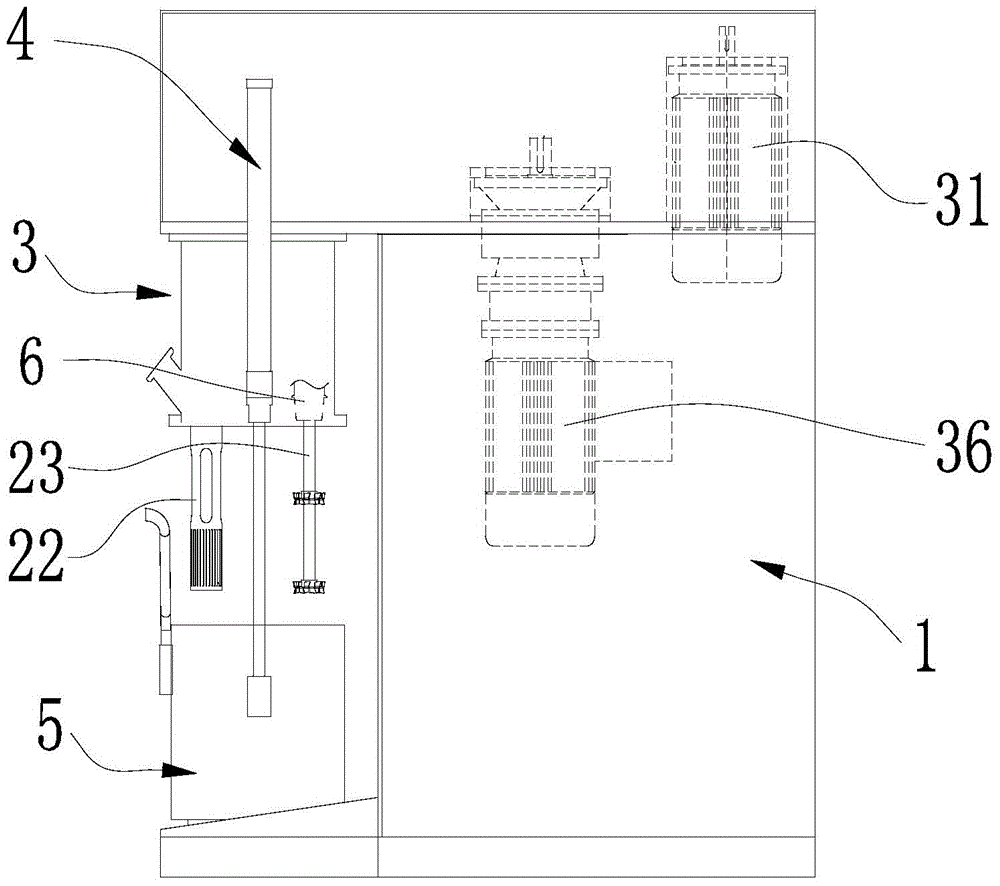
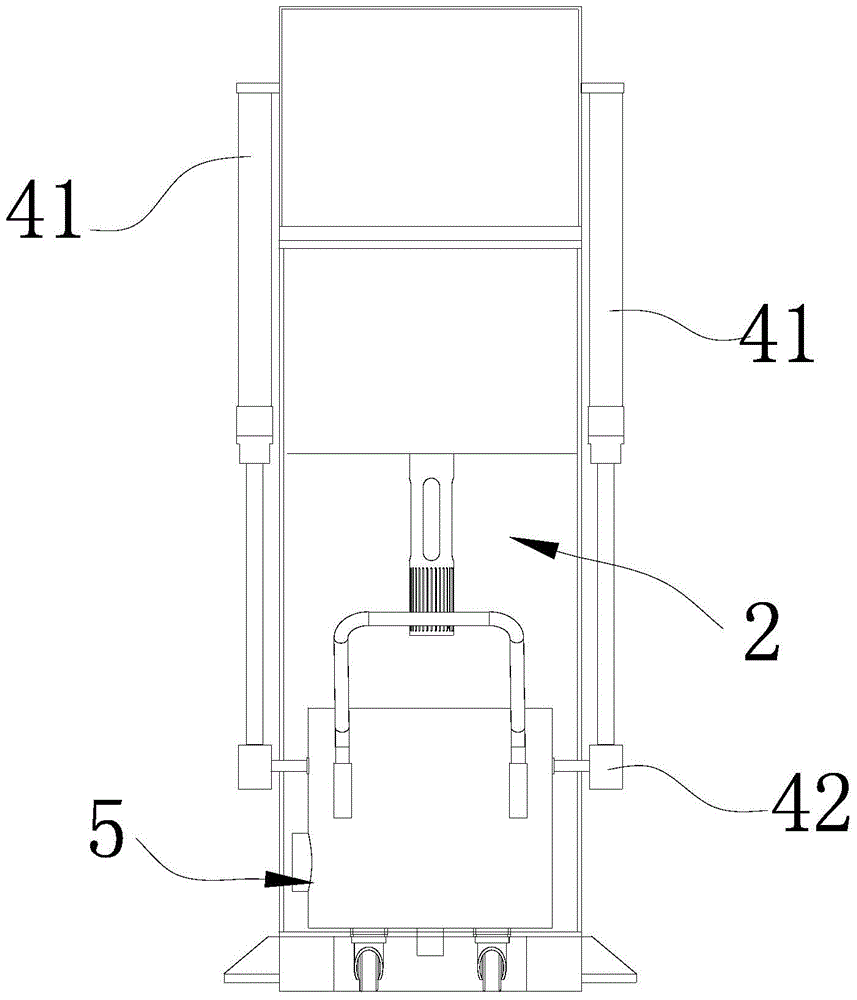
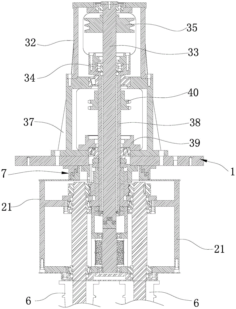
[0024] see Figure 1 to Figure 7 , a kind of high-efficiency dispersing mixer provided by the present embodiment includes a machine base 1, which also includes an efficient dispersing and mixing mechanism 2, a driving mechanism 3 and a lifting device 4 for controlling the up and down movement of the mixing barrel body 5, The driving mechanism 3 is arranged on one side of the machine base 1, the high-efficiency dispersing and mixing mechanism 2 is arranged on the top of the other side of the machine base 1, and is connected with the driving mechanism 3, and the lifting device 4 is arranged on The side of the high-efficiency dispersing and mixing mechanism 2 can smoothly lift the mixing barrel 5 to the predetermined position required by the high-efficiency dispersing and mixing mechanism 2 .

[0025] see figure 2 , the lifting device 4 includes two hydraulic cylinders 41, which are arranged on the base 1 corresponding to the two sides of the high-efficiency dispersion and mixi...


PUM


Abstract

The invention discloses an efficient dispersion mixer. The efficient dispersion mixer comprises a base, and also comprises an efficient dispersion mixing mechanism, a driving mechanism, a power sealer and an elevating device for controlling a stirring barrel body to move up and down. The mixer has a reasonable structure design, and the efficient dispersion mixing mechanism and the driving mechanism are arranged, so materials can be rapidly crushed, dispersed and mixed, the stirring dispersion force is strong, the stirring coverage area is large, and stirring requirements on highly viscose materials are met. The efficient dispersion mixer has the advantages of high working efficiency, good stirring effect, and wide application range, is suitable for being used in the chemical engineering industry, the food industry and the medicine industry, and is especially suitable for material stirring of lithium ion batteries and power batteries; and additionally, the elevating device is adopted to control the rise and fall of the stirring barrel body, so stationary movement, accurate positioning and operation safety guarantee are realized.

Description

technical field [0001] The invention relates to the technical field of mixing, in particular to a high-efficiency dispersing mixer. Background technique [0002] With the rapid development of the national economy, various new materials and new products are constantly emerging. In the manufacturing process of new products, high-efficiency dispersing mixers are widely used in the pharmaceutical industry, chemical industry, food industry, and construction industry. The main types of high-efficiency dispersing mixers are high-speed pusher type and turbine type; low-speed type ribbon type and other frame-type high-efficiency dispersing mixers, etc., but still can not achieve a good mixing effect, the existing problems are: 1 1. There is a bad mixing zone; 2. The mixing time is long, and it takes a long time to stir to crush, disperse and mix the solid particles in the material, and the work efficiency is low; 3. High-speed operation will inhale gas, which is difficult for process...

Claims


Application Information

Patent Timeline
IPC IPC(8): B01F7/30
Inventor 蔡静君
Owner 蔡静君
Learn More