Forced cooling device based on latent heat exchanging

A forced cooling and latent heat technology, applied in the field of heat transfer and heat exchange, can solve the problems of high power consumption, complex structure, and unsafety of radiators, and achieve the effects of high heat exchange intensity, small flow rate of working fluid, and energy saving

Inactive Publication Date: 2015-06-03
NORTHWESTERN POLYTECHNICAL UNIV
View PDF7 Cites 12 Cited by
  • Summary
  • Abstract
  • Description
  • Claims
  • Application Information

AI Technical Summary

Problems solved by technology

[0004] In order to solve the problems of large power consumption, poor effect, unsafe and complex structure of existing large-scale integrated circuit radiators, this invention proposes a forced cooling device based on the principle of latent heat heat exchange

Method used


Image

  • Forced cooling device based on latent heat exchanging
  • Forced cooling device based on latent heat exchanging
  • Forced cooling device based on latent heat exchanging

Examples


Embodiment Construction

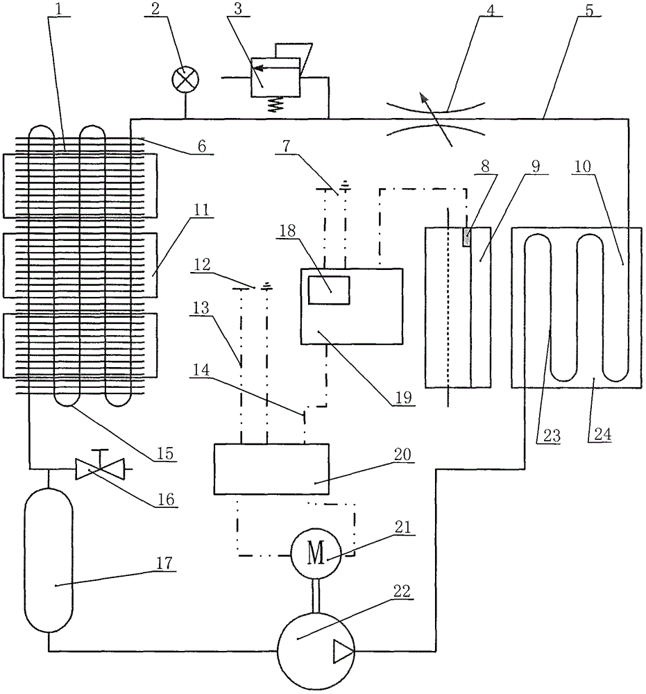
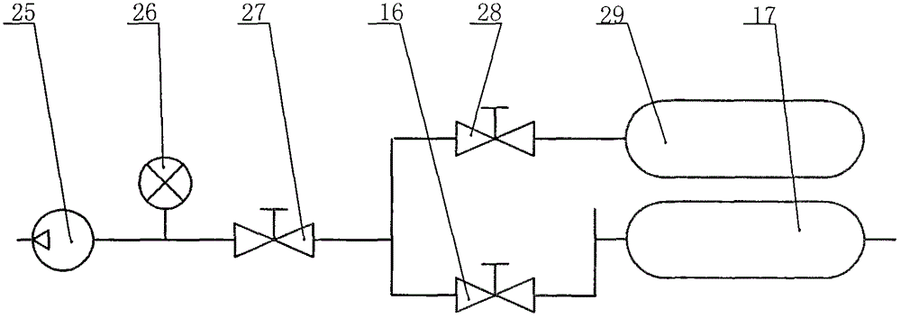
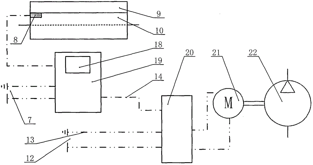
[0019] This embodiment is a forced cooling device based on latent heat exchange.

[0020] refer to Figure 1~3 In this embodiment, a forced cooling device based on latent heat exchange consists of a condenser 1, a pressure gauge 2, a safety valve 3, a restrictor 4, a hose 5, a fin set 6, a 5V DC power supply 7, a temperature sensor 8, Heating unit 9, heat conduction block 10, fan 11, 24V DC power supply 12, wire 13, signal line 14, first S-shaped copper tube 15, first stop valve 16, liquid collector 17, MCU 18, main control unit 19, motor Controller 20, DC motor 21, diaphragm pump 22, second S-shaped copper tube 23, evaporator 24, vacuum pump 25, vacuum gauge 26, second shut-off valve 27, third shut-off valve 28, working fluid storage tank 29. The hoses 5 are DN8mm polytetrafluoroethylene high-pressure hoses, and the adapters of the pipelines 5 are quick-plug connectors; the opening pressure of the safety valve 3 is 1.0Mpa, the range of the pressure gauge 2 is 1.2Mpa, and the...


PUM


Abstract

A forced cooling device based on latent heat exchanging comprises a high-temperature evaporator, a low-temperature condenser, a throttle, a delivery pump, a liquid trap, a safety valve, a stop valve, a temperature control system and a working medium filling device which are connected through high-pressure hoses. The phase change latent heat of working media is used to take away heat, and the forced cooling device is mainly used for solving the radiation problems of large-power electronic components. The delivery pump delivers the liquid working media in the liquid trap to the evaporator, the liquid working media absorb heat and is gasified, the gaseous working media flow into the condenser, is liquefied and release heat to the environment, and liquid working media converge into the liquid trap under gravity action. The temperature control system controls the rotation speed of the delivery pump through the temperature feedback at a cold end and a hot end, and accordingly the heat exchanging power of a working medium flow control device. The safe and nontoxic R134a is used as the working media, and equipment and the environment cannot be damaged even leakage occurs.

Description

technical field [0001] The invention relates to the technical field of heat transfer and heat exchange, in particular to a forced heat exchange device based on latent heat utilization. Background technique [0002] With the development of integrated circuit technology and microelectronics technology, various small-sized, highly integrated electronic products continue to emerge. However, highly integrated circuit systems must face the problem of insufficient heat dissipation. The current heat dissipation problem has become a limitation for the development of electronic products and integrated circuits. One of the bottleneck technologies. At present, for the heat dissipation of large-scale integrated circuits such as high-performance workstations and servers on the market, there are mainly two solutions: air-cooled and water-cooled. The cooling function mainly depends on the temperature rise of air or water to remove heat. Taking the workstation mainframe as an example, the m...

Claims


Application Information

Patent Timeline
Patent Type & Authority Applications(China)
IPC IPC(8): F28D15/02
Inventor 黄闯李代金罗凯
Owner NORTHWESTERN POLYTECHNICAL UNIV
Why Eureka
Try Eureka