Eureka AIR delivers breakthrough ideas for toughest innovation challenges, trusted by R&D personnel around the world.

Double stop-band triangular ultra wideband patch antenna based on phase step resonator

A step resonator and patch antenna technology, which is applied in the directions of antenna coupling, antenna grounding device, antenna grounding switch structure connection, etc., can solve the problem of large system capacity, etc.

Inactive Publication Date: 2015-06-03
HARBIN FEIYU TECH
View PDF0 Cites 0 Cited by
  • Summary
  • Abstract
  • Description
  • Claims
  • Application Information

AI Technical Summary

Problems solved by technology

③Large system capacity

Method used


Image

  • Double stop-band triangular ultra wideband patch antenna based on phase step resonator
  • Double stop-band triangular ultra wideband patch antenna based on phase step resonator
  • Double stop-band triangular ultra wideband patch antenna based on phase step resonator

Examples


Embodiment Construction

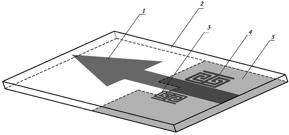
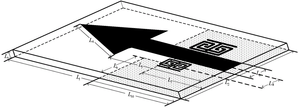
[0018] Since the step resonator-based triangular UWB patch antenna with dual stop bands works in the microwave frequency band, its radiation principle will be analyzed here with the help of microwave transmission line theory. Assume that the side length of the triangular radiating element of the patch antenna is half wavelength λ / 2, and the thickness of the dielectric substrate is L 3 . In this way, the triangular radiating element, the dielectric substrate and the grounding plate can be regarded as a low-impedance microstrip transmission line with a length of λ / 2, and an open circuit is formed at the edge of the radiating element. And because the thickness of the dielectric substrate is much smaller than the wavelength λ, the component of the electric field along the normal direction of the patch plane basically does not change. In the case of only considering the excitation of the main mode, the electromagnetic wave radiation can basically be considered to be caused by the ...


PUM


Abstract

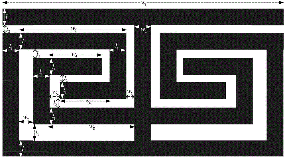
The invention relates to a double stop-band triangular ultra wideband patch antenna based on a phase step resonator. The double stop-band triangular ultra wideband patch antenna based on the phase step resonator comprises a patch antenna 1 (comprising a regular triangular radiation unit and a feeder line), a dielectric substrate 2, a 3.5 GHz phase step resonator 3, a 5.6 GHz phase step resonator 4 and a grounding plate 5; the double stop-band triangular ultra wideband patch antenna is characterized in that resonation structures are arranged on the two sides of the feeder line of the antenna to realize the double band-notched function; the radiation unit of the antenna is of a regular triangular patch structure, and the grounding plate is partially tailored. The double stop-band triangular ultra wideband patch antenna realizes the ultra wideband transmission characteristic ( VSWRand lt; 2) from 3.1 GHz to 10.6 GHz, and respectively forms stop bands in the two narrow bands of 3.4 GHz - 3.7 GHz (WLAN frequency band) and 5.4 GHz - 6.0 GHz (WiMAX frequency band), so that the interference between the two frequency bands is effectively reduced.

Description

technical field [0001] The invention relates to a double-stop-band triangular ultra-wideband patch antenna based on a step resonator. A resonant structure is added to both sides of the antenna feeder to realize a double-notch function. The antenna radiation unit is an equilateral triangle patch structure, and the floor is ground Partially cropped. The antenna achieves ultra-wideband transmission characteristics (VSWR<2) from 3.1GHz to 10.6GHz, and forms stop bands in two narrowband frequency bands of 3.4-3.7GHz (WLAN frequency band) and 5.4-6.0GHz (WiMAX frequency band), effectively The interference with the two frequency bands is reduced. Background technique [0002] Ultra-wideband communication technology is widely used in the fields of radar, positioning, electronic countermeasures, and secure communication. It has long been regarded as a cutting-edge military technology and closely guarded by various countries. It has not been gradually used by civilians until recen...

Claims


Application Information

Patent Timeline
IPC IPC(8): H01Q1/38H01Q1/48H01Q1/50H01Q1/52
Inventor 刘雷刘文剑吴永飞
Owner HARBIN FEIYU TECH
Why Eureka
Eureka Blog
Learn More