Optical signal synchronizing system

A technology of synchronous system and optical signal, which is applied in the field of laser communication, can solve the problem of unfixed repetition frequency of output pulse, achieve the effect of ensuring confidentiality and anti-interference performance, and improving sensitivity and accuracy

Inactive Publication Date: 2015-06-03
INST OF SEMICONDUCTORS - CHINESE ACAD OF SCI
View PDF0 Cites 3 Cited by
  • Summary
  • Abstract
  • Description
  • Claims
  • Application Information

AI Technical Summary

Problems solved by technology

[0003] However, due to the certain response time when the saturable absorbing material reaches absorption saturation, the pump laser wavelength changes with the temperature rise, etc., the output pulse has an unfixed repetition frequency.

Method used


Image

  • Optical signal synchronizing system

Examples


Embodiment Construction

[0010] In order to make the object, technical solution and advantages of the present invention clearer, the present invention will be further described in detail below in conjunction with specific embodiments and with reference to the accompanying drawings.

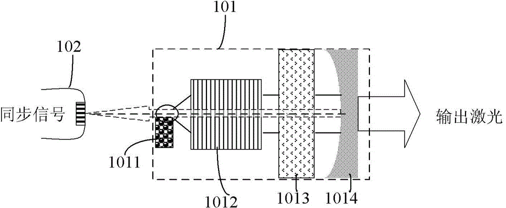
[0011] figure 1 A schematic structural diagram of a system for optical signal synchronization using a passive Q-switched solid-state laser proposed by the present invention is shown. Such as figure 1 As shown, the optical signal synchronization system includes: a passive Q-switched solid-state laser 101 and a photodetector 102, wherein the passive Q-switched solid-state laser includes a pump source 1011, a laser crystal 1012, a Q-switched crystal 1013 and a cavity mirror 1014 ; The pumping source 1011 emits pumping light from the front, and the laser crystal 1012, Q-switched crystal 1013 and cavity mirror 1014 form a resonant cavity of the laser on the optical path of the pumping light, and the pumping source 1011 emits ...


PUM


Abstract

The invention discloses an optical signal synchronizing system which comprises a passive Q modulation solid laser and an optical-electric detector, wherein the passive Q modulation solid laser comprises a pumping source, laser crystal, Q modulation crystal and a cavity lens; the laser crystal, Q modulation crystal and the cavity lens form a resonant cavity of the laser; the pumping source is used for generating pumping light from the front side of the pumping source; the pumping light is injected into the laser crystal so as to generate laser; the laser is amplified through the resonant cavity and is emitted out from the cavity surfaces at two ends of the resonant cavity; the optical-electric detector is positioned at the back of the pumping source, and is used for detecting laser emitted from the cavity surface of the rear end of the resonant cavity, so that an optical signal synchronous with laser emitted from the passive Q modulation solid laser from cavity surface of the front end of the resonant cavity is obtained. By adopting the optical signal synchronizing system, not only is a collimation structure of the laser ensured, but also the confidentiality and the anti-interference property of output pulse can be ensured, and the application of integration of the passive Q modulation solid laser is improved.

Description

technical field [0001] The invention relates to the technical field of laser communication, in particular to an optical signal synchronization system, which is suitable for a passive Q-switched solid-state laser with a laser diode as a pumping source. Background technique [0002] Passive Q-switching method, because the Q switch is activated by the laser radiation itself, only needs a saturable absorbing material, no high voltage, electro-optic driver or radio frequency modulator, and has the advantages of simple design, small size, low cost, long life, and high efficiency. It is especially suitable for lasers with high repetition rate, high power and narrow pulse, and has broad application prospects in the fields of laser ranging, tracking, target indication, laser detection and submarine communication. [0003] However, due to the certain response time when the saturable absorbing material reaches absorption saturation, the wavelength of the pump laser changes with the tem...

Claims


Application Information

Patent Timeline
Patent Type & Authority Applications(China)
IPC IPC(8): H01S3/094H01S3/11
Inventor 徐荣韩海
Owner INST OF SEMICONDUCTORS - CHINESE ACAD OF SCI
Why Eureka
Try Eureka