Air separation machine for powder coating production
A powder coating, air separator technology, applied in the direction of separating solids from solids with air flow, solid separation, filtration, etc.
- Summary
- Abstract
- Description
- Claims
- Application Information
AI Technical Summary
Problems solved by technology
Method used
Image
Examples
Embodiment 1
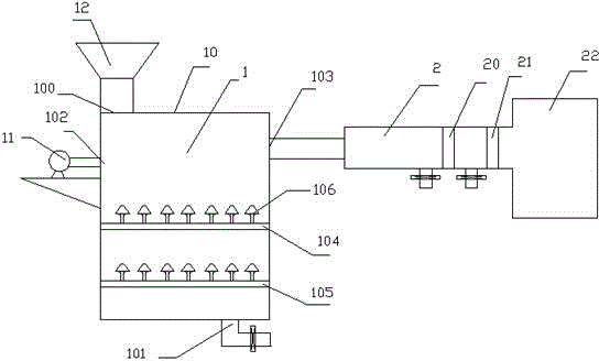
[0021] The present embodiment comprises winnowing box 1 and winnowing tank 2, and winnowing tank 2 is connected on winnowing box 1, and described winnowing box 1 comprises box body 10 and blower 11, and the top of described box body 10 is provided with feed outlet 100, the bottom of the box body 10 is provided with a discharge port 101, the upper part of the box body 10 is provided with a blower port 102 and a suction port 103, an upper screen 104 and a lower screen 105 are installed in the box body 10, and the blower 11 is installed on On the box body 10, the air blower 11 is connected on the blast port 102 of the box body 10 through a pipeline, and the air selection tank 2 is connected to the air suction port 103 of the box body 1 through a pipeline, and the pipeline between the air suction port 103 and the air selection tank 2 An exhaust fan is installed inside, a left sieve 20 and a right sieve 21 are installed in the winnowing tank 2 , and a collector 22 is connected to th...
Embodiment 2
[0023] The present embodiment comprises winnowing box 1 and winnowing tank 2, and winnowing tank 2 is connected on winnowing box 1, and described winnowing box 1 comprises box body 10 and blower 11, and the top of described box body 10 is provided with feed outlet 100, the bottom of the box body 10 is provided with a discharge port 101, the upper part of the box body 10 is provided with a blower port 102 and a suction port 103, an upper screen 104 and a lower screen 105 are installed in the box body 10, and the blower 11 is installed on On the box body 10, the air blower 11 is connected on the blast port 102 of the box body 10 through a pipeline, and the air selection tank 2 is connected to the air suction port 103 of the box body 1 through a pipeline, and the pipeline between the air suction port 103 and the air selection tank 2 An exhaust fan is installed inside, a left sieve 20 and a right sieve 21 are installed in the winnowing tank 2 , and a collector 22 is connected to th...
Embodiment 3
[0025] The present embodiment comprises winnowing box 1 and winnowing tank 2, and winnowing tank 2 is connected on winnowing box 1, and described winnowing box 1 comprises box body 10 and blower 11, and the top of described box body 10 is provided with feed outlet 100, the bottom of the box body 10 is provided with a discharge port 101, the upper part of the box body 10 is provided with a blower port 102 and a suction port 103, an upper screen 104 and a lower screen 105 are installed in the box body 10, and the blower 11 is installed on On the box body 10, the air blower 11 is connected on the blast port 102 of the box body 10 through a pipeline, and the air selection tank 2 is connected to the air suction port 103 of the box body 1 through a pipeline, and the pipeline between the air suction port 103 and the air selection tank 2 An exhaust fan is installed inside, a left sieve 20 and a right sieve 21 are installed in the winnowing tank 2 , and a collector 22 is connected to th...
PUM
 Abstract
Description
Claims
Application Information
 - R&D
- Intellectual Property
- Life Sciences
- Materials
- Tech Scout
- Unparalleled Data Quality
- Higher Quality Content
- 60% Fewer Hallucinations
Browse by: Latest US Patents, China's latest patents, Technical Efficacy Thesaurus, Application Domain, Technology Topic, Popular Technical Reports.
© 2025 PatSnap. All rights reserved.Legal|Privacy policy|Modern Slavery Act Transparency Statement|Sitemap|About US| Contact US: help@patsnap.com


