
Blunt trailing edge type wind turbine blade as well as implementing device and method thereof

A wind turbine and blunt trailing edge technology is applied in the field of lamination design and process realization of wind turbine blades, can solve the problems of low constitutive strength bonding interface strength, increased trailing edge strength, etc., and achieves compact trailing edge structure, The effect of small additional bending moment and improved bonding strength

Active Publication Date: 2015-06-10
INST OF ENGINEERING THERMOPHYSICS - CHINESE ACAD OF SCI
View PDF10 Cites 18 Cited by
  • Summary
  • Abstract
  • Description
  • Claims
  • Application Information

AI Technical Summary

Problems solved by technology

Compared with laminated composite materials, the constitutive strength of the bonded structural adhesive and the strength of the bonding interface are relatively low, and the trailing edge of the blade is subject to large wielding shear stress and torsional shear stress, and the trailing edge is bound to become the weak link of the blade structure , while the hand lay-up reinforced layer is limited by the aerodynamic shape, internal operating space and the process itself, so the substantial increase in the strength of the trailing edge is often outweighed by the gain

Method used


Image

  • Blunt trailing edge type wind turbine blade as well as implementing device and method thereof
  • Blunt trailing edge type wind turbine blade as well as implementing device and method thereof
  • Blunt trailing edge type wind turbine blade as well as implementing device and method thereof

Examples


Embodiment Construction

[0057] In order to make the objectives, technical methods and advantages of the present invention more clear, the present invention will be further described in detail below in conjunction with specific embodiments and with reference to the accompanying drawings.

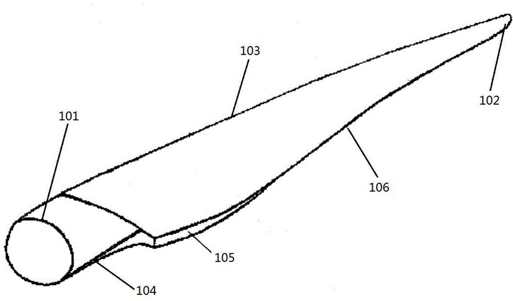
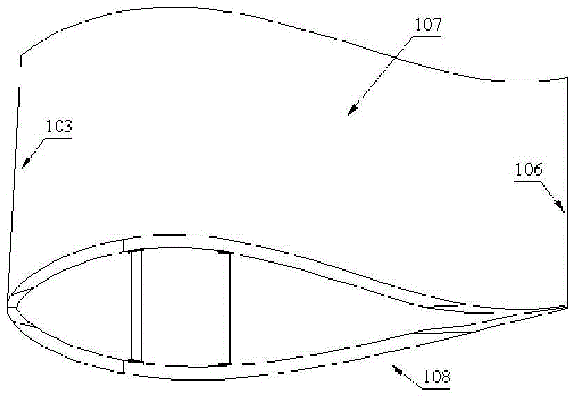
[0058] like figure 1 , 2 As shown, the fiber-reinforced composite material wind turbine blunt trailing edge blade of the present invention includes a blade leading edge 103, a pressure side shell 107 and a suction side shell 108, such as figure 1 As shown, the blade trailing edge includes a cylindrical trailing edge 104 of the root section, a pointed trailing edge 106 of the tip section, and a blunt trailing edge 105 in the middle.

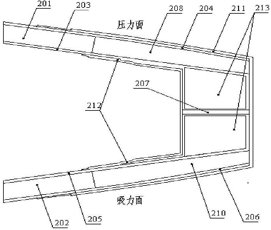
[0059] like image 3 As shown, the blunt trailing edge of the existing blunt trailing edge blade includes a pressure surface part, a suction surface part and a vertical part structure, and the pressure surface part includes a trailing edge core material 201, an inner skin 203, an oute...


PUM


Abstract

The invention discloses a blunt trailing edge type wind turbine blade and a processing method thereof. The blade is made of a fiber laminating composite; trailing edge reinforced fiber single layers at the blunt trailing edge part are alternately laid along a pressure surface trailing edge line and a blunt trailing edge vertical part; reinforced fiber single layers at the sharp tailing edge part close to a blade tip are retracted towards the inner side of a die in a tangential direction and then laid to guarantee appropriate die closing clearance; as many reinforced fiber single layers as possible at the round tailing edge part close to a blade root get close to the tailing edge line in the tangential direction to guarantee an enough bonding width for die closing; the laying positions of the reinforced fiber laying layers in the blunt trailing edge vertical part can be flexibly designed according to demand of structural performance, and additional laying layers and laying layer angles can be increased. The trailing edge structure of the blade has higher connection strength and engineering operability, and trailing edge cracking and trailing edge instability can be effectively inhibited.

Description

technical field [0001] The invention relates to a wind turbine blade layup design and process realization thereof, in particular to a blunt trailing edge layup design, forming method and process implementation device of a fiber-reinforced composite wind turbine blade, which belongs to the design and manufacture of wind turbine blades methods and technical fields. Background technique [0002] As a member of the new energy family, wind energy plays an important role in promoting the diversification of energy supply and protecting the ecological environment. Especially in recent years, with the advancement of technology, in order to make full use of wind energy and improve the cost of electricity, wind turbines stand-alone With the continuous increase of capacity, the blades of wind turbines are getting longer and longer. The structure, aerodynamic performance and product quality of blades have become one of the key factors to measure the service performance of wind turbines. ...

Claims


Application Information

Patent Timeline
Patent Type & Authority Applications(China)
IPC IPC(8): F03D11/00
CPCB29C33/00B29C70/34B29C70/54B29C70/543F03D1/0675Y02E10/72
Inventor 秦志文陈啸杨科徐宇廖猜猜荣晓敏
Owner INST OF ENGINEERING THERMOPHYSICS - CHINESE ACAD OF SCI
Learn More