Optical Fiber Interference Water Level Sensor
A water level sensor, optical fiber interference technology, applied in the direction of instruments, liquid level indicators, machines/engines, etc., can solve the problems of short service life, large error, limited transmission distance, etc., to achieve simple and exquisite structure, long service life, The effect of long transmission distance
- Summary
- Abstract
- Description
- Claims
- Application Information
AI Technical Summary
Problems solved by technology
Method used
Image
Examples
Embodiment 1
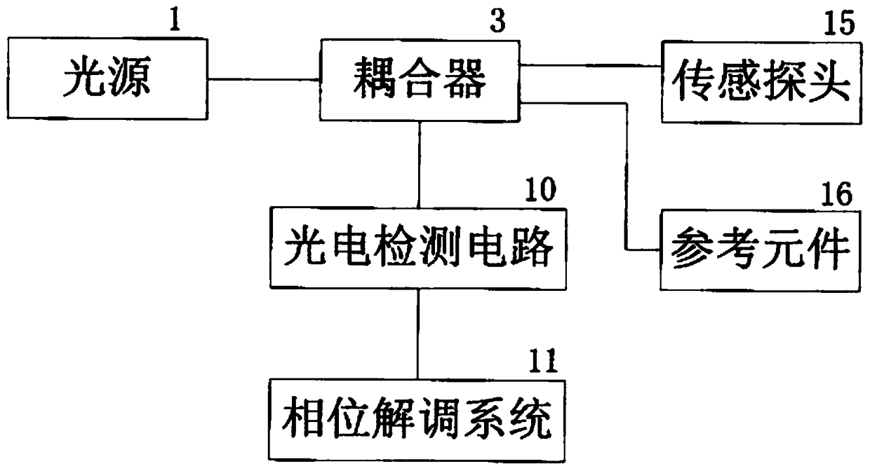
[0026] like figure 1 Shown is a system block diagram of a water level sensor based on fiber optic interferometry. The invention includes six parts: a light source module, a coupler, a sensing probe, a reference element, a photoelectric detection circuit, and a phase demodulation system. The light emitted by the light source enters the coupler, and the coupler divides the light into two paths. One path of light enters the sensor probe and is reflected back, and the other path passes through the reference element and is reflected back. The output end of the coupler is connected to the photoelectric detection circuit. The output signal of the photoelectric detection circuit enters the phase demodulation system for demodulation. Finally, the change of the water level is obtained by inversion of the phase difference change obtained from the demodulation.
Embodiment 2
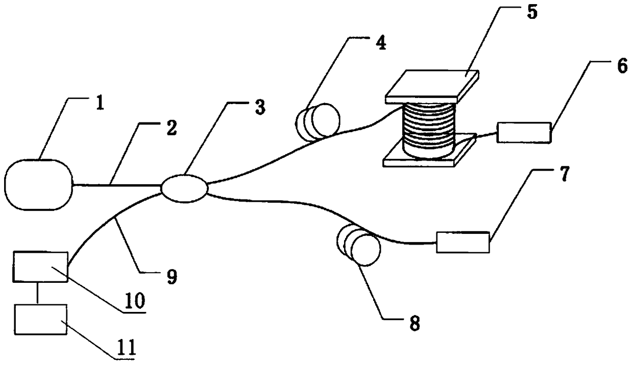
[0028] like figure 2 As shown, a water level sensor structure diagram based on optical fiber interferometry. The sensor structure includes a semiconductor laser 1, a light-guiding single-mode fiber 2, 4, 9, a 3dB coupler 3, a sensitive element 5, a first Faraday rotator 6, a second Faraday rotator 7, a reference fiber 8, and a photodetector 10 . It is characterized in that: the input end of the 3dB coupler 3 is connected to the semiconductor laser 1, and the output end of the coupler 3 is divided into two paths, one of which is connected to the sensitive element 5 and the first Faraday rotation mirror 6 through the single-mode fiber 4 to form a detection arm; The other path is directly connected to the second Faraday rotation mirror 7 via a single-mode optical fiber 8 to form a reference arm, and the 3dB coupler 3 is connected to the photodetector 10 via the light-guiding optical fiber 9, and the signal output by the photodetector 10 is collected by the acquisition card , E...
Embodiment 3
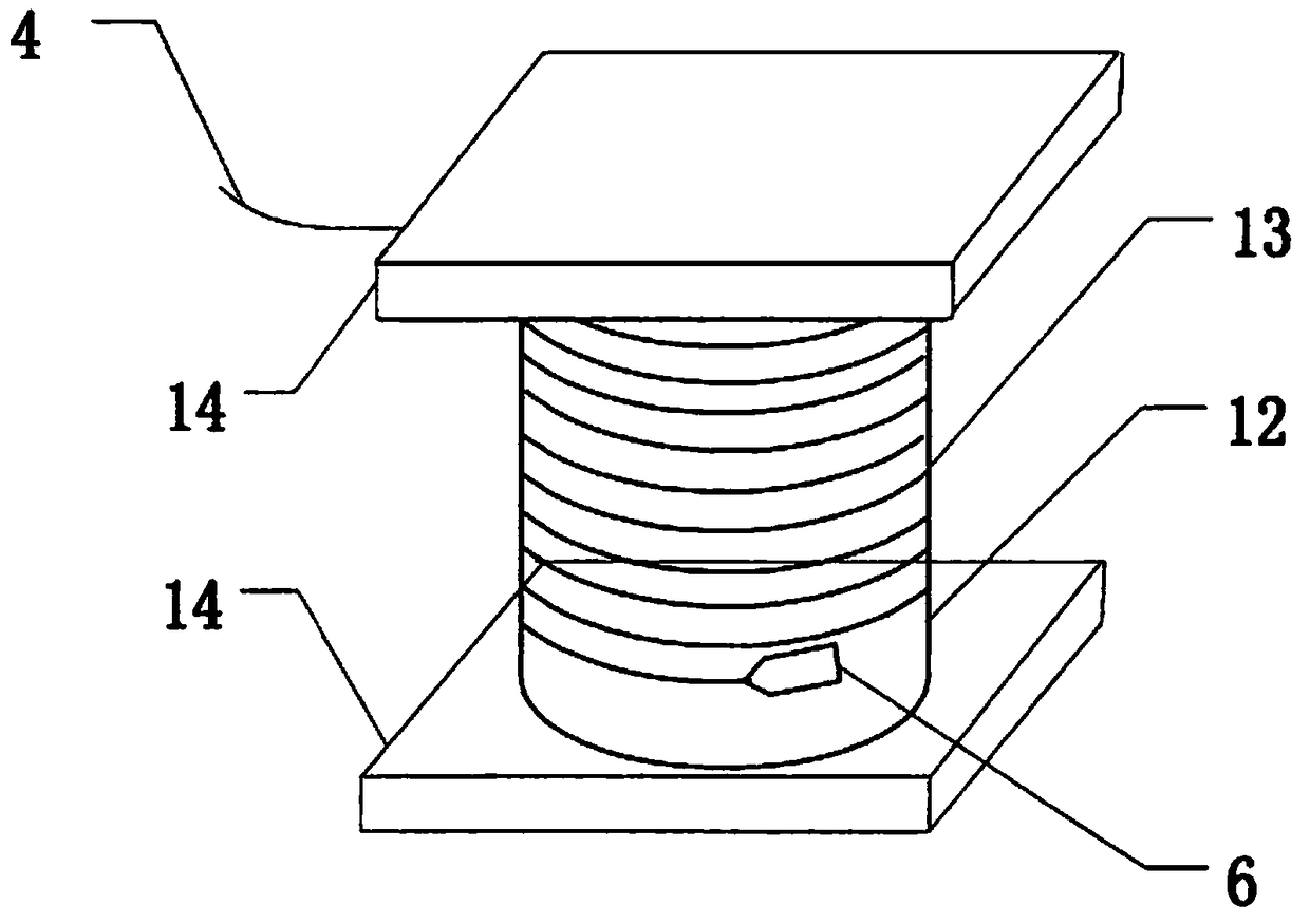
[0031] like image 3 , Figure 4 Shown is the sensitive element of the optical fiber interference water level sensor, and the structure diagram and section diagram of the sensing probe. exist image 3 , clearly shows that the sensitive element is a structure in which the single-mode detection fiber 13 is tightly wound around the variable cylinder 12, and one end of the detection fiber is connected to the first Faraday rotation mirror 6, and the other end is connected to the light guide fiber 4, and the upper and lower sides of the silica gel cylinder Two stainless steel thin plates 14 are fixed on the surface. The role of the stainless steel sheet is to increase the force-bearing area of the sensing probe in the water, thereby increasing the sensitivity of the sensitive element. The compliance cylinder is a key part of the sensitive element, and its conversion efficiency and performance directly determine the characteristics of the sensitive element. The reason for choosi...
PUM
 Abstract
Description
Claims
Application Information
 - R&D
- Intellectual Property
- Life Sciences
- Materials
- Tech Scout
- Unparalleled Data Quality
- Higher Quality Content
- 60% Fewer Hallucinations
Browse by: Latest US Patents, China's latest patents, Technical Efficacy Thesaurus, Application Domain, Technology Topic, Popular Technical Reports.
© 2025 PatSnap. All rights reserved.Legal|Privacy policy|Modern Slavery Act Transparency Statement|Sitemap|About US| Contact US: help@patsnap.com


