
Fiber optic coherent ranging device and method

A technology of fiber optics and ranging devices, applied in measuring devices, radio wave measuring systems, electromagnetic wave re-radiation, etc., can solve problems such as measurement failure, inability to reflect light, and difficulty in forming coherent fringes, etc., to reduce optical path alignment requirements, the effect of expanding the scope of application

Inactive Publication Date: 2015-06-10
上海舜宇海逸光电技术有限公司
View PDF0 Cites 10 Cited by
  • Summary
  • Abstract
  • Description
  • Claims
  • Application Information

AI Technical Summary

Problems solved by technology

However, due to its own characteristics, the existing optical ranging technology encounters corresponding challenges in accurate ranging from submicron to tens of millimeters.
Ranging methods such as laser radar are only suitable for long-distance measurement; traditional coherent optical ranging requires the surface to be measured to be smooth to form a plane reflection, and the requirements for optical path alignment are very strict, and the small angular offset of the measured surface relative to the measuring light will cause Measurement failed
[0003] In the research of the coherent ranging technology, the applicant found that a surface with a certain roughness, such as a metal processing surface, cannot reflect light like an optical surface. Scattered light is generated in the spatial angle range, and the propagation direction of the scattered light is scattered, and the coherence is reduced
The combination of two parts of light scattered from different surfaces will hardly form coherent fringes, making coherent measurements impossible

Method used


Image

  • Fiber optic coherent ranging device and method
  • Fiber optic coherent ranging device and method
  • Fiber optic coherent ranging device and method

Examples


Embodiment Construction

[0023] The embodiments of the present invention will be described in detail below with reference to the accompanying drawings, but the present invention can be implemented in many different ways defined and covered by the claims.

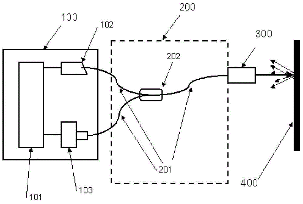
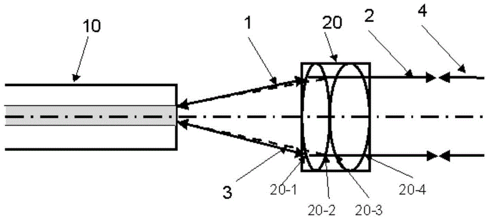
[0024] The optical fiber optical coherence measurement method of the present invention applies the optical filtering characteristics of the single-mode optical fiber, and couples the light reflected or scattered from the measured surface into the single-mode optical fiber core and couples the light reflected from the reference surface into the same single-mode optical fiber core coherence of the light, because two parts of light scattered or reflected from different positions are coupled into the fiber core at the same time, the two parts of light are spatially filtered by the fiber core, and their spatial coherence is restored, scattered or reflected from different positions and coupled The two parts of light entering the fiber core will be well coh...


PUM


Abstract

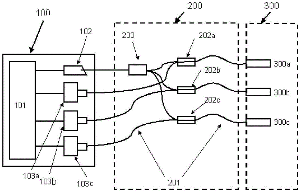
The invention discloses a fiber optic coherent ranging device and method. The fiber optic coherent ranging device comprises a demodulation unit with wavelength scanning, an optical head and an SMF (single mode fiber) conduction unit. The SMF conduction unit is used for conducting laser, transmitted from the demodulation unit, to the optical head. The optical head comprises a collimating lens system and a reference plane. The collimating lens system is used for collimating the laser outputted from a fiber end face of the SMF conduction unit. The reference plane is used for reflecting a part of the laser collimated back to the fiber end face and coupling the same into an SMF. The demodulation unit is used for detecting coherent light in the SMF and, according to the coherent light, calculating distance between the reference plane and a surface to be detected, to be specific, the coherent light is formed by cohering light, reflected or scattered from the surface to be detect, and light , reflected from the reference plane, which are coupled in the same SMF. By the use of the fiber optic coherent ranging device and method, ranging of non-optical reflection surfaces such as non-polished metal and plastic surfaces is achieved.

Description

technical field [0001] The invention relates to a fiber optic coherent distance measuring device and a fiber optic distance measuring method. Background technique [0002] Ranging is widely used in the field of modern industrial automation, and long-distance optical ranging is widely favored because it has no hidden danger of electric sparks and has good safety features in special explosive environments such as oil and gas. However, due to its own characteristics, the existing optical distance measurement technology encounters corresponding challenges in accurate distance measurement in the range of submicron to tens of millimeters. Distance measurement methods such as lidar are only suitable for long-distance measurement; traditional coherent optical distance measurement requires the surface to be measured to be smooth to form a plane reflection, and the requirements for optical path alignment are very strict. Measurement failed. [0003] The applicant found in the resear...

Claims


Application Information

Patent Timeline
IPC IPC(8): G01S17/32
CPCG01S17/32
Inventor 袁海骏杨德志周伟凌清任伟王克银
Owner 上海舜宇海逸光电技术有限公司
Learn More