Low-RCS (radar cross section) microstrip patch antenna based on polarization conversion

A technology of microstrip patch antenna and polarization conversion, which is applied in the direction of antenna, antenna grounding switch structure connection, radiation element structure, etc., can solve the problems of high radar cross section and poor scattering characteristics, and achieve low radar cross section and good scattering Features, Effects of Eliminating Effects

Inactive Publication Date: 2015-06-10
XIDIAN UNIV
View PDF2 Cites 12 Cited by
  • Summary
  • Abstract
  • Description
  • Claims
  • Application Information

AI Technical Summary

Problems solved by technology

Through reasonable optimization design, this antenna can achieve good radiation characteristics, but because the size of the metal floor of the microstrip patch antenna is larger than the radiation unit, there are defects of high radar cross section and poor scattering characteristics

Method used


Image

  • Low-RCS (radar cross section) microstrip patch antenna based on polarization conversion
  • Low-RCS (radar cross section) microstrip patch antenna based on polarization conversion
  • Low-RCS (radar cross section) microstrip patch antenna based on polarization conversion

Examples


Embodiment 1

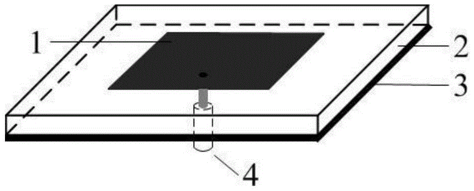
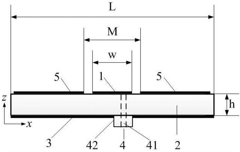
[0030] refer to figure 2 , the present invention includes a radiation unit 1 , a dielectric plate 2 , a metal floor 3 , a coaxial joint 4 and a polarization conversion surface 5 . The dielectric plate 2 is made of a dielectric material with a dielectric constant of 4.4, a side length L of 80 mm, and a thickness h of 2 mm; a radiation unit 1 is printed on the geometric center of the upper surface of the dielectric plate 2, and the radiation unit 1 adopts a square shape. The metal patch has a side length w of 15.6 mm, and a polarization conversion surface 5 is printed on the upper surface of the dielectric plate 2 around the radiation unit 1 . A metal floor 3 is printed on the lower surface of the medium plate 2 , and the shape and size of the metal floor 3 are the same as those of the medium plate 2 . A via hole is provided near the center of the dielectric board 2 , through which the inner core 41 of the coaxial connector 4 is welded to the radiation unit 1 , and the outer c...

Embodiment 2

[0035] Embodiment 2 has the same structure as Embodiment 1, only some parameters are adjusted.

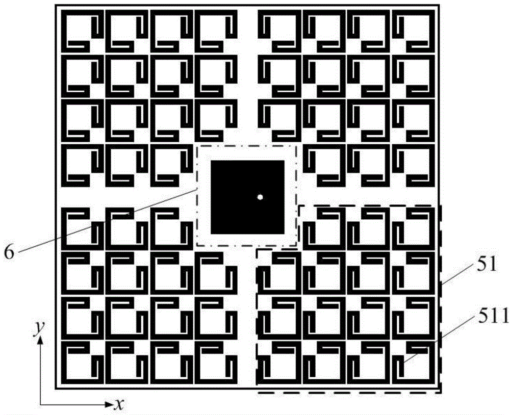
[0036] The side length M of the square region 6 is 19 mm; the line width S3 of the polarization conversion unit 511 is 0.9 mm

Embodiment 3

[0038] Embodiment 3 has the same structure as Embodiment 1, only some parameters are adjusted.

[0039] The side length M of the square region 6 is 20 mm; the line width S3 of the polarization conversion unit 511 is 1.1 mm

[0040] Advantage of the present invention can be further illustrated by the simulation of embodiment 1:

[0041] 1. Simulation content

[0042] 1.1) Utilize the commercial simulation software CST Microwave Studio 2011 to simulate the S parameter of the polarization conversion unit 511 of the above-mentioned embodiment 1 in the range of 3.0-12.0GHz, the result is as follows Figure 5 shown.

[0043] 1.2) Utilize commercial simulation software CST Microwave Studio 2011 to carry out simulation calculation to the S parameter of above-mentioned embodiment 1 in the scope of 4.0-4.6GHz, the result is as follows Image 6 shown.

[0044] 1.3) Utilize the commercial simulation software CST Microwave Studio 2011 to carry out the simulation calculation of the far-fi...


PUM


Abstract

The invention discloses a low-RCS microstrip patch antenna based on polarization conversion. The low-RCS microstrip patch antenna based on polarization conversion is used for solving the defect of poor scattering performance of existing microstrip patch antennas. The low-RCS microstrip patch antenna based on polarization conversion comprises a radiating unit (1), a dielectric slab (2), a metal ground slab (3), a coaxial joint (4) and a polarization conversion surface (5). The upper surface and the lower surface of the dielectric slab (2) are printed with the radiating unit (1), and the polarization conversion surface (5) as well as the metal ground slab (3) respectively; the polarization conversion surface (5) is composed of four polarization conversion unit groups (51), and the center of the polarization conversion surface (5) is provided with a square area (6); every polarization conversion unit group (51) comprises a plurality of polarization conversion units (511) with the symmetric axises provided with square notches (512) which point to the same direction. The low-RCS microstrip patch antenna based on polarization conversion has the advantages of being stable in radiating performance and high in scattering performance and can serve as a communication antenna on a low-RCS device.

Description

technical field [0001] The invention belongs to the technical field of antennas, and relates to a microstrip patch antenna with a low radar cross section, in particular to a microstrip patch antenna which reduces the radar cross section by applying a polarization conversion structure. Under the premise of ensuring the radiation performance of the antenna, it has Good scattering properties. It is suitable for radar systems that require both radiation and scattering characteristics. Background technique [0002] In various communication systems, the antenna is an important part of the radar system, and its radar cross section is the main contributor to the overall radar cross section of the aircraft. Since the antenna, as a communication device, first needs to ensure the normal reception and emission of its own electromagnetic waves, so the conventional technology of reducing the radar cross section is not suitable for the reduction of the radar cross section of the antenna. ...

Claims


Application Information

Patent Timeline
Patent Type & Authority Applications(China)
IPC IPC(8): H01Q1/38H01Q13/08H01Q1/50
Inventor 刘英郝玉文申博龚书喜
Owner XIDIAN UNIV
Why Eureka
Try Eureka