Automatic welding device for auger stem fin

An automatic welding and auger rod technology, applied in auxiliary devices, welding equipment, auxiliary welding equipment, etc., can solve the problems of low welding operation efficiency, difficult to guarantee welding quality, high labor intensity, etc., and achieve high welding operation efficiency and adjustment. Simple, convenient and highly automated

Inactive Publication Date: 2015-06-17
HARBIN LONGFEI WELDING EQUIP
View PDF6 Cites 4 Cited by
  • Summary
  • Abstract
  • Description
  • Claims
  • Application Information

AI Technical Summary

Problems solved by technology

[0002] At present, when the helical blade and the blade shaft are welded together by gas shielded welding, it is generally used to position the helical blade on the blade shaft by spot welding first, and then clamp the blade shaft on the machine tool using the cooperation of the headstock and the tailstock. , using the rotating power of the bedside box to drive the blade shaft to rotate, and the welder holds the welding gun to complete the welding operation between the spiral blade and the blade shaft along the helical line of the spiral blade. In addition to the problems of high labor intensity and low welding efficiency, the welding quality is not easy Guarantee is a technical problem that must be solved

Method used


Image

  • Automatic welding device for auger stem fin
  • Automatic welding device for auger stem fin

Examples


Embodiment Construction

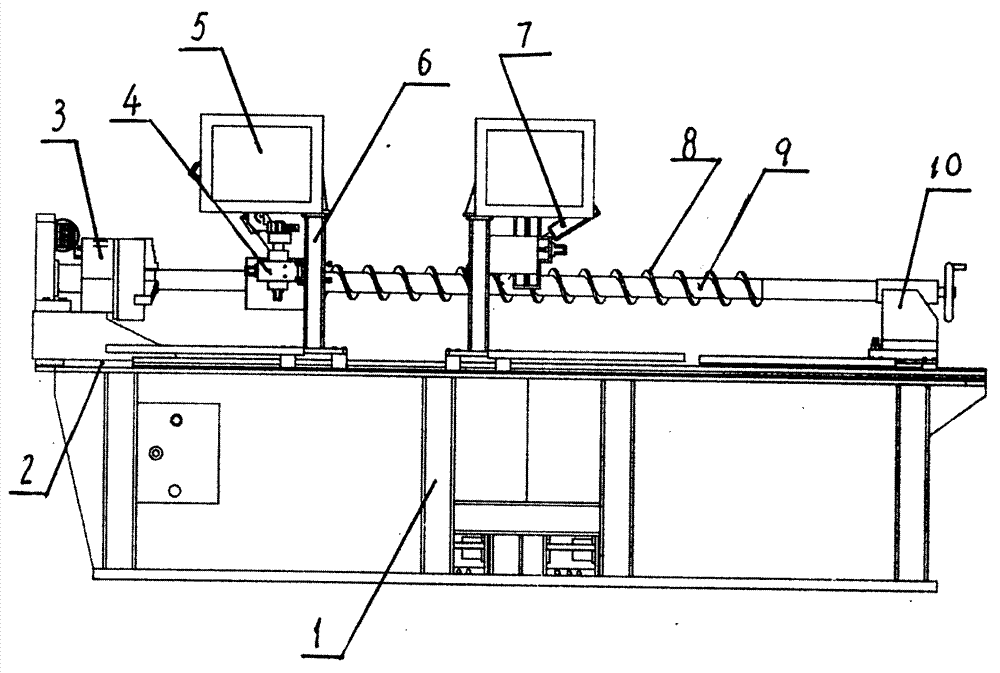
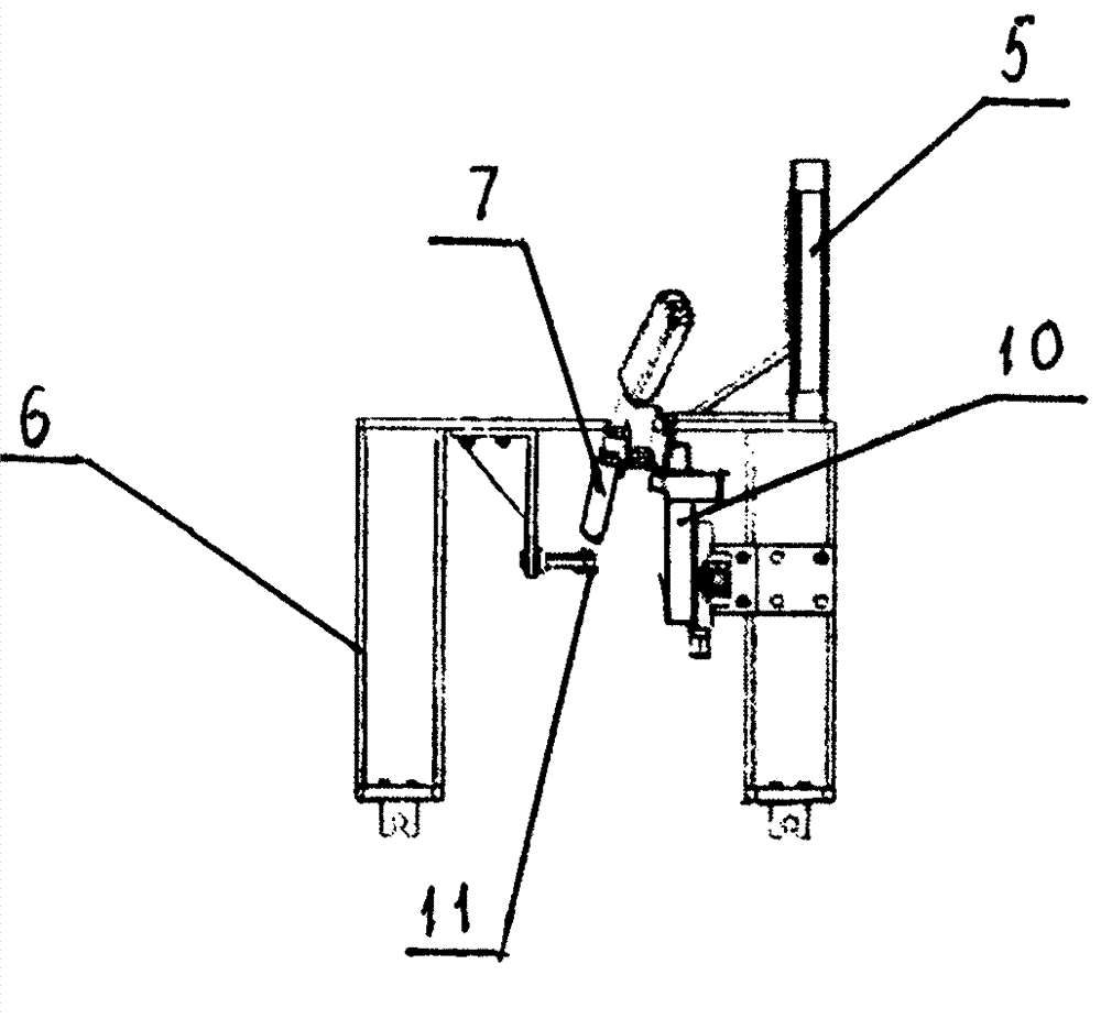
[0010] Embodiments of the present invention will be described in detail below in conjunction with the accompanying drawings. An automatic welding device for auger pipe fins includes a bed 1, on which a guide rail 2 is fixed, a headstock 3 is fixed on the left side of the bed 1, and a tailstock 0 is arranged on the On the right side of the bed 1, two moving frames 6 are fitted on the bed 1 in cooperation with the guide rail 2 and can move left and right laterally, and the fine-tuning assembly 4, arc-proof plate 5 and rollers are installed on the moving frame 6 11. The welding torch 7 is installed on the trimming assembly 4.

[0011] When the operation is in use, the blade shaft 9 that has been spot-welded and positioned on the blade shaft 9 with the spiral fin 8 is clamped and installed on the headstock 3 and the tailstock 10, and then the two rollers 11 on the two mobile frames 6 are respectively Contact and cooperate with the opposite sides of the helical fins 8, and then ad...


PUM


Abstract

The invention provides an automatic welding device for an auger stem fin, and belongs to welding equipment. The automatic welding device for the auger stem fin comprises a machine body, a guide rail, a headstock box and a tailstock, wherein the guide rail, the headstock box and the tailstock are assembled on the machine body. Two movable frames which are matched with the guide rail and can transversely move are assembled on the machine body. Fine adjustment assemblies, anti-arc light boards and idler wheels are arranged on the movable frames. Welding guns are installed on the fine adjustment assemblies. By the adoption of the automatic welding device, the auger stem fin and a fin shaft are automatically welded in a gas protective welding mode, the structure is simple, the automation degree and welding operation efficiency are high, adjustment is easy and convenient, welding operation quality is good, operation labor intensity is low, and the application range is wide.

Description

technical field [0001] The invention belongs to welding equipment, and mainly relates to a welding device used for welding a spiral blade and a blade shaft. Background technique [0002] At present, when the helical blade and the blade shaft are welded together by gas shielded welding, it is generally used to position the helical blade on the blade shaft by spot welding first, and then clamp the blade shaft on the machine tool using the cooperation of the headstock and the tailstock. , using the rotating power of the bedside box to drive the blade shaft to rotate, and the welder holds the welding gun to complete the welding operation between the spiral blade and the blade shaft along the helical line of the spiral blade. In addition to the problems of high labor intensity and low welding efficiency, the welding quality is not easy Guarantee is a technical problem that must be solved. Contents of the invention [0003] The purpose of the present invention is to solve the p...

Claims


Application Information

Patent Timeline
Patent Type & Authority Applications(China)
IPC IPC(8): B23K37/02B23K37/047
CPCB23K37/0211B23K37/047
Inventor 汪一雄高秋梅
Owner HARBIN LONGFEI WELDING EQUIP
Why Eureka
Try Eureka