Power storage device and super capacitor device

A technology for supercapacitors and energy storage components, which is applied in capacitors, electrolytic capacitors, double-layer capacitors, etc., and can solve problems that affect component capacity retention, failure to achieve functional addition effects, long-term cycle characteristics, and power performance.

Active Publication Date: 2015-06-17
IND TECH RES INST
View PDF4 Cites 0 Cited by
  • Summary
  • Abstract
  • Description
  • Claims
  • Application Information

AI Technical Summary

Problems solved by technology

[0004] However, the adhesive itself is usually not a good conductor of electricity, and the stability of the potential change during the charge-discharge cycle greatly affects the long-term cycle and capacity retention performance of the device.
[0005] In the past research on supercapacitors, in order to improve the energy density, lithium-ion battery electrode materials and electric double-layer electrode materials were often used in combination. However, the two materials in the same electrode layer usually cause lithium-ion competition and cannot achieve the desired function. Therefore, many studies have begun to coat electrodes with two different functional orientations individually to form double-layer electrodes.
However, the layer sequence of this double-layer structure has its own advantages and disadvantages: when the electrical double-layer material is bonded to the electrical substrate, the junction resistance can be reduced, but the lithium-ion battery material in the outer layer also increases the lithium-ion diffusion resistance; on the contrary, the electrical double-layer material Although placed in the outer layer is beneficial to absorb liquid and reduce the reaction between lithium-ion battery materials and electrolyte, it also reduces the power characteristics of the electrode due to the high junction resistance of the lower layer
[0006] The above studies are also relatively indifferent to long-term cycle characteristics and power performance

Method used


Image

  • Power storage device and super capacitor device
  • Power storage device and super capacitor device
  • Power storage device and super capacitor device

Examples


Embodiment Construction

[0049] In order to make the object, technical solution and advantages of the present invention clearer, the present invention will be further described in detail below in conjunction with specific embodiments and with reference to the accompanying drawings.

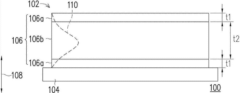
[0050] figure 1 is a schematic cross-sectional view of an energy storage element according to an embodiment of the present invention.

[0051] Please refer to figure 1 , the energy storage element 100 of this embodiment at least includes a positive electrode and a negative electrode 102, wherein the energy storage element 100 can be a lithium battery, a capacitor, a solar battery or a lead-acid battery, and those with ordinary knowledge in the field of energy storage technology can According to the difference of the components, other components are added in it. The positive electrode and the negative electrode 102 in this embodiment are located on one side of a current collector foil 104 , but they can also be provided ...


PUM


Abstract

A power storage device includes a positive electrode and a negative electrode disposed opposite to the positive electrode. The positive electrode and the negative electrode are respectively disposed on at least one surface of a current collector foil. The positive electrode and the negative electrode respectively include an active material, a conductive auxiliary and an adhesive, wherein the active material includes a porous material, an oxidation-reduction electrode material, or combination thereof. At least one of the positive electrode and the negative electrode has a multilayer structure containing three or more layers. The concentration of the oxidation-reduction electrode material in the outmost layer of the multilayer structure is the lowest.

Description

technical field [0001] The present invention relates to an energy storage device, and in particular to an energy storage element and a supercapacitor (supercapacitor, SC) element. Background technique [0002] Supercapacitor (SC) is also known as electrical double layer capacitor (EDLC), its energy storage is to use electrostatic energy as an energy storage type, in recent years, research has particularly focused on its high power output performance and Energy storage and conversion. EDLC energy storage and release come from the electric double layer structure formed by electrostatic charge adsorption. Such an electric double layer mechanism has an excellent reversible charge and long-term charge-discharge cycle performance maintenance rate because there is almost no loss of electrolyte and electrodes during the electrochemical reaction process, and its long-term cycle life can be guaranteed. more than tens of thousands of times. [0003] Since the area of ​​the electric ...

Claims


Application Information

Patent Timeline
IPC IPC(8): H01G11/22H01G11/00
CPCH01M4/131H01M4/505H01M10/0525H01M2004/021H01M10/06H01M4/133H01M4/14H01G11/02H01G11/04Y02E60/13H01G11/28H01G11/46H01G11/32Y02E60/10
Inventor 林育威蔡丽端方家振黄震宇
Owner IND TECH RES INST
Why Eureka
Try Eureka