Reinforcing structure of reinforced concrete arch bridge main arch ring

A technology of reinforced concrete and reinforced structure, applied in the direction of bridge reinforcement, arch bridges, bridges, etc., can solve the problems of the influence of traffic conditions under the bridge, high consumption, long cost recovery period, etc., to reduce the overall labor intensity and improve the compressive bearing capacity , the effect of reducing the overall working hours

Active Publication Date: 2015-06-24
XIAN UNIV OF SCI & TECH
View PDF9 Cites 15 Cited by
  • Summary
  • Abstract
  • Description
  • Claims
  • Application Information

AI Technical Summary

Problems solved by technology

Problems such as high energy consumption and long cost recovery cycle when under the bridge, and have a significant impact on the traffic conditions under the bridge

Method used


Image

  • Reinforcing structure of reinforced concrete arch bridge main arch ring
  • Reinforcing structure of reinforced concrete arch bridge main arch ring
  • Reinforcing structure of reinforced concrete arch bridge main arch ring

Examples


Embodiment 1

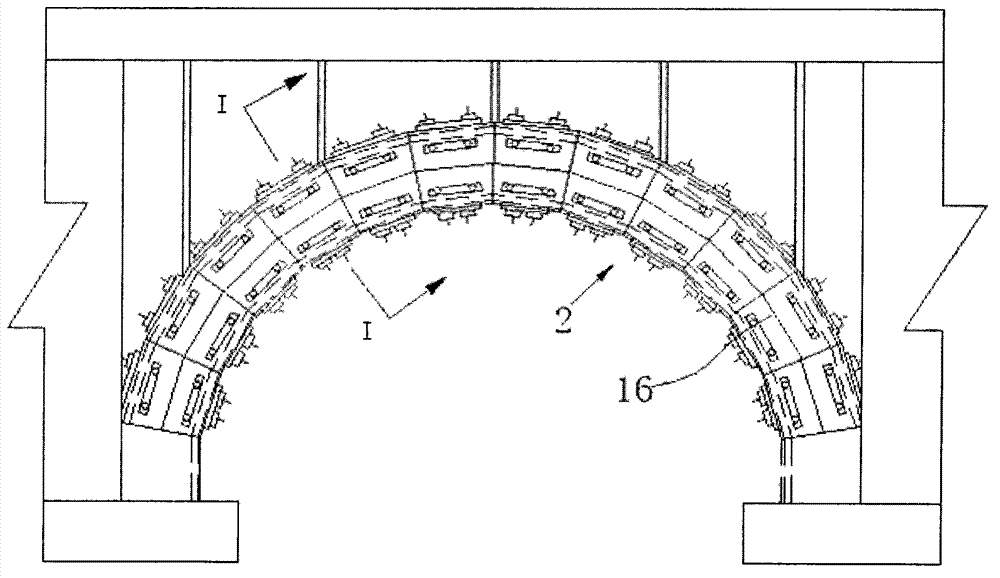
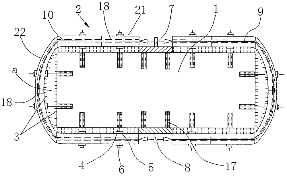
[0026] see Figure 1-6 , a reinforcement structure for the main arch ring of a reinforced concrete arch bridge, which includes a prefabricated concrete surface formwork 2 extending along the concrete main arch circle 1 direction of the arch bridge, the surface formwork 2 is composed of several formwork sections 16, and the formwork sections 16 It is a formwork system composed of a circle of formworks connected to each other. The middle parts of the top and bottom sides of the formwork section 16 are respectively fixed with a first steel anchor box 7 and a second steel anchor box 8 arranged symmetrically. Between the first steel anchor box 7 and the second steel anchor box 8, the surface template working section 16 is integrally tensioned and fixed into one by the first prestressed steel strand 9 and the second prestressed steel strand 10, and the template Working section 16 is made up of plane formwork 21 and arc formwork 22, and the middle part of described plane formwork 21 ...

Embodiment 2

[0039] see Figure 1-6 , a construction method for reinforcing the main arch ring of a reinforced concrete arch bridge, which is realized through the following steps:

[0040] 1) Clean up the damaged concrete surface of the concrete main arch ring 1 of the arch bridge, roughen the surface, and plant shear pins 3 to ensure that the old and new concrete work together;

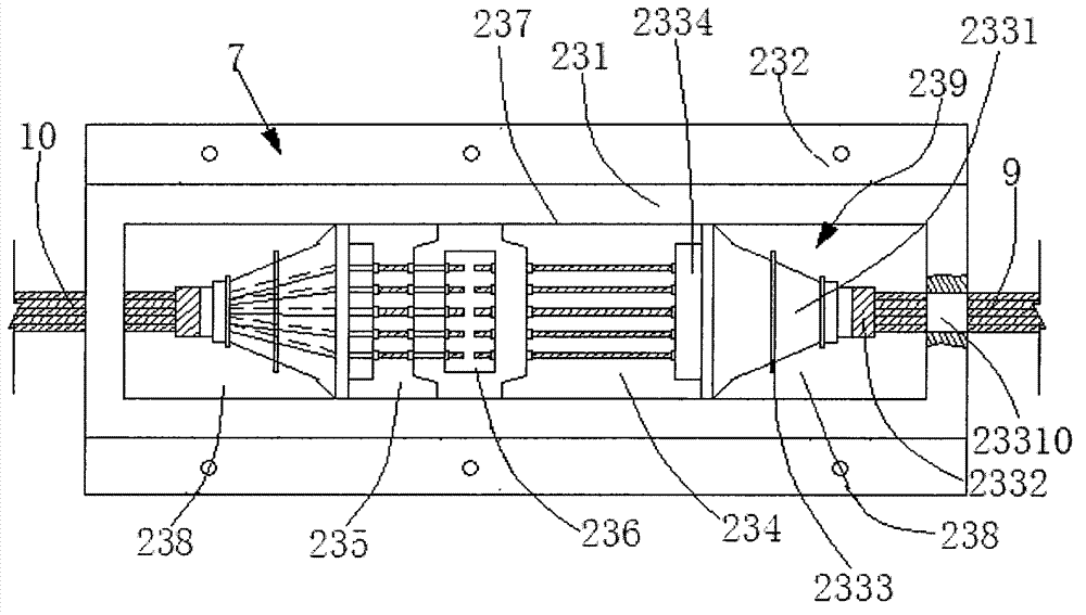
[0041] 2) Find out the center line of the top and bottom surfaces of each formwork section 16 of the arch bridge concrete main arch ring 1, and then implant threaded steel bars 17 on the upper top surface and lower bottom surface of the center line of the arch bridge concrete main arch ring 1 working section, and then pass the threaded steel bars Fix the pre-embedded load-bearing plate, weld and fix the force-transmitting steel plate 231 in the first steel anchor box 7 or the second steel anchor box 8 and the load-bearing plate (finally pouring concrete to wrap the first steel anchor box 7 or the second steel anc...


PUM


Abstract

The invention discloses a reinforcing structure of a reinforced concrete arch bridge main arch ring. The reinforcing structure comprises a prefabricated concrete surface formwork (2) extending in the axial direction of the concrete arch bridge main arch ring (1), the surface formwork (2) is composed of multiple formwork working sections (16) which are a formwork system formed by combining a circle of formworks connected mutually, a first steel anchor box (7) and a second steel anchor box (8) symmetrical to the first steel anchor box (7) are fixed to the middles of the top faces and the middles of the bottom faces of the formwork working sections (16) respectively, and the formwork working sections (16) are provided with a circumferential prestressing steel strand. Due to the fact that the formwork-disassembling-free circumferential prestressing reinforcing technology is adopted, the cross section of the main arch ring is subjected to circumferentially-distributed squeezing force and tangential dragging force, the overall working hours are reduced, the overall labor intensity is lowered, the economic benefit is improved, and meanwhile the radial compression resistance and bearing capability of the main arch ring is effectively improved.

Description

technical field [0001] The invention relates to the technical field of reinforcement of main arch rings on reinforced concrete arch bridges. Background technique [0002] In the reinforcement of the main arch ring of reinforced concrete arch bridges, the commonly used reinforcement methods for the main arch ring include: spray anchor reinforcement, reinforced concrete mold injection reinforcement, reinforcement with steel plates or steel bars, reinforcement with fiber materials, etc., and the variants of the above types of reinforcement, among which Reinforced concrete mold injection reinforcement method is the most widely used in reinforcement of reinforced concrete arch bridge superstructure due to its less construction difficulty. Wait. High consumption, long cost recovery period and other issues, and have a significant impact on the traffic conditions under the bridge. Contents of the invention [0003] The purpose of the present invention is to provide a reinforceme...

Claims


Application Information

Patent Timeline
Patent Type & Authority Applications(China)
IPC IPC(8): E01D22/00E01D4/00E01D101/28
CPCE01D4/00E01D22/00E01D2101/285
Inventor 李博渊
Owner XIAN UNIV OF SCI & TECH
Why Eureka
Try Eureka