

Metal honeycomb carrier structure used for catalyst
A metal honeycomb carrier and catalyst technology, applied in catalyst carriers, physical/chemical process catalysts, chemical instruments and methods, etc., can solve problems affecting service life, cracking and damage, etc., to extend service life, reduce thermal stress, increase internal The effect of surface area
- Summary
- Abstract
- Description
- Claims
- Application Information
AI Technical Summary
Problems solved by technology
Method used
Image

Examples
Embodiment 1
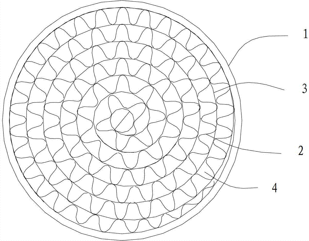
[0018] refer to figure 2 , is a metal honeycomb carrier structure for catalysts, including an outer sleeve 1, a plurality of honeycomb holes 4 arranged in the outer sleeve 1 and surrounded by overlapping and rolling of planar plates 3 and corrugated plates 2, on one side of the honeycomb holes 4 An inflection point 5 is provided on the corrugated plate 2 of the side.
[0019] When in the working state, when the corrugated plate 2 is thermally expanded and deformed, its deformation direction is not limited to the circular direction, and the deformation from the inflection point 5 is increased, thereby reducing its deformation in the circular direction, which is consistent with the extension of the flat plate 3 The lengths are matched, thereby reducing the stress on the corrugated plate 2 and improving the cracking condition.
Embodiment 2
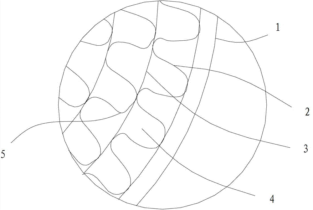
[0021] refer to image 3 , is another kind of metal honeycomb carrier structure for catalysts, including an outer sleeve 1, a plurality of honeycomb holes 4 arranged in the outer sleeve 1 and surrounded by overlapping and rolling of planar plates 3 and corrugated plates 2, one of the honeycomb holes 4 An inflection point portion 5 is provided on the corrugated plate 2 on one side, and a symmetrical inflection point portion 6 is provided on the corrugated plate 2 on the other side of the honeycomb hole 4 . The shape of a single honeycomb hole 4 is Ω-shaped.
[0022] When in the working state, when the corrugated plate 2 is thermally expanded and deformed, in addition to the elongation in the circular direction, the deformation direction can also be deformed from the inflection point 5 and the inflection point 6, thereby significantly reducing its deformation in the circular direction. The amount of deformation matches the elongation of the flat plate 3, thereby reducing the st...
Embodiment 3
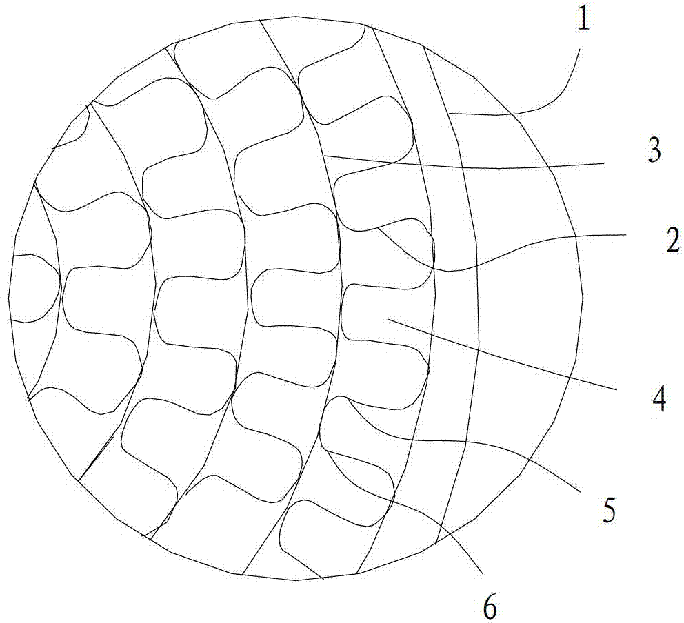
[0024] refer to Figure 4 , which is another metal honeycomb support structure for catalysts, including an outer sleeve 1, a plurality of honeycomb holes 4 arranged in the outer sleeve 1 and surrounded by overlapping rolling of planar plates 3 and corrugated plates 2, one honeycomb hole 4 Inflection point portions 5 are respectively provided at the two end points of the side, and inflection point portions 6 are respectively provided at the two end points of the other side of the honeycomb hole 4 . The shape of a single side of the honeycomb hole 4 is arc-shaped.
[0025] When in the working state, when the corrugated plate 2 is thermally expanded and deformed, in addition to the elongation in the circular direction, the deformation direction can also be deformed from the inflection point 5 and the inflection point 6, thereby significantly reducing its deformation in the circular direction. The amount of deformation matches the elongation of the flat plate 3, thereby reducing ...
PUM
 Abstract
Description
Claims
Application Information