Convection-bank heat exchange set for flue gas waste heat recovery

A convection tube bundle and flue gas technology, applied in the field of convection tube bundle heat exchange equipment and waste heat utilization equipment, can solve problems such as large horse-drawn trolleys and low steam output, and achieve thermal expansion and contraction, investment reduction, and prolong service life. Effect

Inactive Publication Date: 2015-06-24
JIANGSU HONGHUA HEAVY IND
View PDF0 Cites 2 Cited by
  • Summary
  • Abstract
  • Description
  • Claims
  • Application Information

AI Technical Summary

Problems solved by technology

However, the actual steam output is far lower than the maximum evaporation capacity of the waste heat system, resulting in the situation of large horses and small carts

Method used


Image

  • Convection-bank heat exchange set for flue gas waste heat recovery
  • Convection-bank heat exchange set for flue gas waste heat recovery

Examples


Embodiment Construction

[0013] The present invention will be further described below in conjunction with the drawings.

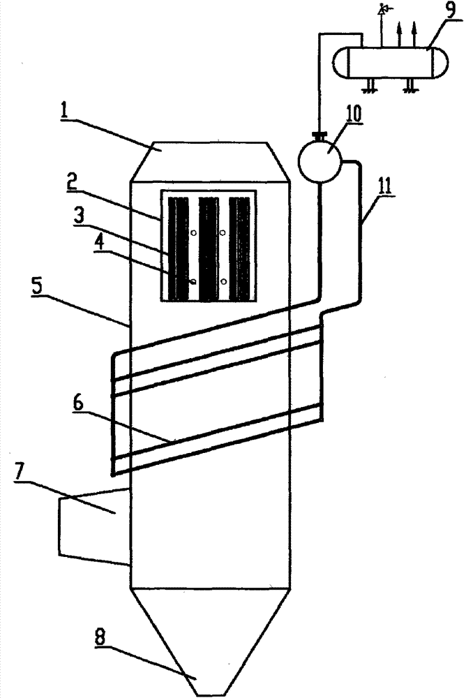
[0014] In the present invention, a convection tube bundle heat exchange device for recovery of flue gas waste heat includes flue gas inlet 1, heat storage homogenizer 2, flue gas passage 5, convection tube bundle 6, flue gas outlet 7, ash hopper 8. Circulation pipeline 11, steam drum 10, steam accumulator 9, characterized in that: the top of the flue gas channel 5 is provided with a flue gas inlet 1, and the bottom of the flue gas channel 5 is provided with a flue gas outlet 7 and a flue gas channel 5 An ash hopper 8 is provided at the bottom, a convection tube bundle 6 is provided inside the flue gas channel 5, and the convection tube bundle 6 is connected to a steam drum 10 through a circulation pipe 11, and the steam drum 10 is connected to a steam accumulator 9 through a pipe. The steam drum 10 is provided with At the top of the outer side of the flue gas channel 5, the heat stora...


PUM


Abstract

A convection-bank heat exchange set for flue gas waste heat recovery comprises a flue gas inlet, a heat-accumulating temperature homogenizer, a flue gas passage, a convection pipe bank, a flue gas outlet, an ash hopper, a circulation pipe, a steam drum and a steam accumulator. The convection-bank heat exchange set is characterized in that the top of the flue gas passage is provided with the flue gas inlet, the outside of the bottom of the flue gas passage is provided with the flue gas outlet, the bottom of the flue gas passage is provided with the ash hopper, the convection pipe bank is disposed in the flue gas passage and is connected with the steam drum through the circulation pipe, the steam drum is connected with the steam accumulator through a pipe, the steam drum is disposed on the top of the outside of the flue gas passage, the heat-accumulating temperature homogenizer is disposed at the upper end of the convection pipe bank within the flue gas passage and comprises carbon-carbon composite accumulating members and a shock wave ash-remover, and the shock wave ash-remover is disposed among the carbon-carbon composite accumulating members segment by segment. The convection-bank heat exchange set has the advantages that heat in the flue gas can be recovered to the maximum extent, investment on waste heat utilization equipment is lower and the waste heat utilization equipment is more stable.

Description

Technical field [0001] The invention relates to a waste heat utilization equipment, in particular to a convection tube bundle heat exchange equipment used for flue gas waste heat recovery, and belongs to the technical field of flue gas waste heat utilization. Background technique [0002] Electric furnace flue gas is currently commonly used waste heat utilization facilities: water tube waste heat boilers, heat pipe waste heat boilers to recover waste heat of electric furnace flue gas and generate saturated steam. Due to the violent fluctuations in the temperature of the electric furnace flue gas and the large amount of dust, it is difficult for ordinary water tube waste heat boilers to be used for the waste heat recovery of the electric furnace flue gas. At present, heat pipe waste heat boilers have been successfully used in electric furnace flue gas waste heat recovery. However, due to the inherent defects of heat pipes (high cost, non-freezing resistance, high temperature resis...

Claims


Application Information

Patent Timeline
Patent Type & Authority Applications(China)
IPC IPC(8): F27D17/00
CPCY02P10/25Y02P80/15
Inventor 梁洪波
Owner JIANGSU HONGHUA HEAVY IND
Why Eureka
Try Eureka