
Rotor structure of a high-speed permanent magnet synchronous motor

A permanent magnet synchronous motor and rotor structure technology, applied in synchronous machine parts, magnetic circuit shape/style/structure, magnetic circuit rotating parts, etc. problems, to reduce the cost of the motor, suppress the current distortion, and optimize the manufacturing process.

Active Publication Date: 2017-09-29
中国船舶重工集团公司第七一二研究所
View PDF4 Cites 0 Cited by
  • Summary
  • Abstract
  • Description
  • Claims
  • Application Information

AI Technical Summary

Problems solved by technology

In the sine wave power supply mode, a large number of high-order harmonics are generated due to the mismatch between the back EMF and the power supply, resulting in distortion of the current and lower efficiency of the motor
[0004] If the air-gap magnetic density waveform is optimized by cutting poles, the gap in the magnet needs to be filled with structural materials, the process is more complicated, and it also affects the heat dissipation of the motor rotor

Method used


Image

  • Rotor structure of a high-speed permanent magnet synchronous motor
  • Rotor structure of a high-speed permanent magnet synchronous motor
  • Rotor structure of a high-speed permanent magnet synchronous motor

Examples


Embodiment Construction

[0020] The present invention will be described in further detail below in conjunction with the accompanying drawings.

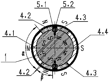
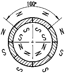
[0021] refer to figure 1 , figure 2 As shown, the invention discloses a rotor structure of a high-speed permanent magnet synchronous motor, including a rotating shaft 1, an end plate 2, a sheath 3 and a magnet 4. The rotating shaft 1 uses a magnetic material to provide a magnetic circuit for the rotor. The rotating shaft 1 The outer surface of the middle section is provided with a groove, and a positioning key 5 is installed in the groove to fix the magnet 4. The positioning key 5 is composed of a flat key 5.1 and a screw 5.2, and is used for positioning the magnet 4 and transmitting torque. The magnetic material is fixed on both sides of the middle section of the rotating shaft 1 through interference fit, and is used for the axial fixation of the magnet 4. After the magnet 4 is installed, the sheath 3 is bound on the outer surface. The sheath 3 is a compos...


PUM


Abstract

The invention discloses a rotor structure of a high-speed permanent-magnet synchronous motor. The rotor structure comprises a rotating shaft, end plates, a protective sleeve and magnets. Grooves are formed in the outer surface of a middle segment of the rotating shaft made of magnetism conducting materials, positioning keys are mounted in the grooves to fix the magnets, the end plates made of non-magnetism-conducting materials are fixed on two sides of the middle segment of the rotating shaft, the magnets include permanent magnets made of two different materials, and the protective sleeve is made of composite materials with carbon fibers serving as a base and is bound on the outer surfaces of the magnets. Compared with a surface-mounted rotor magnetic circuit structure adopted by a traditional high-speed permanent-magnet synchronous motor, the rotor structure of the high-speed permanent-magnet synchronous motor has the advantages that the rotor magnetic circuit structure, air-gap magnetic flux density waveforms, manufacturing techniques and the like are optimized to a great degree, motor cost can be reduced, and the rotor structure is suitable for high-speed permanent-magnet synchronous motors with high requirements on motor performance and with the characteristics of a small number of pole pairs, large-external-diameter rotors and the like.

Description

technical field [0001] The invention belongs to the technical field of motors, and in particular relates to a rotor structure especially suitable for a high-speed permanent magnet synchronous motor with a small number of pole pairs or a large outer diameter of the rotor. Background technique [0002] High-speed permanent magnet synchronous motors usually adopt a surface-type rotor magnetic circuit structure, which has the advantages of simple process and low manufacturing cost. [0003] High-speed permanent magnet synchronous motors generally require that the air-gap magnetic field tends to be sinusoidal. When the number of pole pairs is small or the size is large, the permanent magnets under each pole of the rotor need to be divided into blocks and separated Splicing after magnetization causes the air gap magnetic density under each pole to show the characteristics of a square wave, and the generated back electromotive force also tends to be a square wave. In the sine wave...

Claims


Application Information

Patent Timeline
Patent Type & Authority Patents(China)
IPC IPC(8): H02K1/27H02K21/02
Inventor 张经纬王刚周贵厚张丽民
Owner 中国船舶重工集团公司第七一二研究所
Learn More