Communication equipment metal shell and manufacturing method thereof

A technology for communication equipment and metal shells, applied in the field of metal shells of communication equipment and its preparation, can solve the problems of easy damage, deformation, unfavorable production, etc., and achieve the effect of preventing deformation

Active Publication Date: 2015-06-24
BYD CO LTD
View PDF3 Cites 48 Cited by
  • Summary
  • Abstract
  • Description
  • Claims
  • Application Information

AI Technical Summary

Problems solved by technology

[0005] The technical problem to be solved by the present invention is to provide a communication equipment metal shell for the problems in the prio...

Method used


Image

  • Communication equipment metal shell and manufacturing method thereof
  • Communication equipment metal shell and manufacturing method thereof

Examples


preparation example Construction

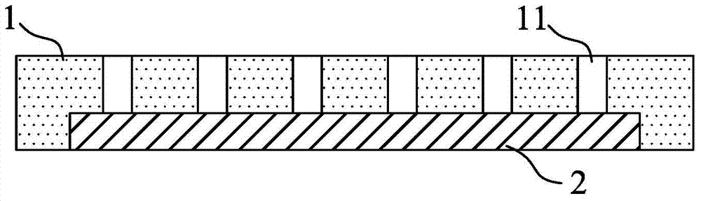
[0036] The metal shell of the communication equipment provided by the present invention can be prepared by the following preparation method, which specifically includes:

[0037] S1. Provide a metal substrate, the metal substrate is provided with a plurality of slits; the width of the slit is 5-40 μm, and the distance between two adjacent slits is 0.3-1.6 mm;

[0038]S2. Roughening the inner surface of the metal matrix at the position where the gap is located to form a metal shell; there are multiple micropits on the inner surface of the metal shell;

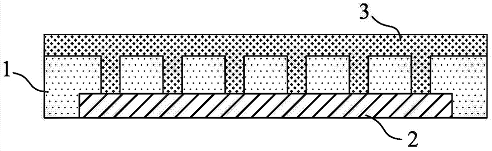
[0039] S3. Inject resin on the inner surface of the metal shell where the gap is located to form a plastic part.

[0040] In step S1, the metal base can be purchased or obtained by self-processing. It only needs to satisfy that the width of the slit on the metal base is 5-40 μm, and the distance between two adjacent slits is 0.3-1.6 mm.

[0041] If it is processed by itself, various existing cutting methods can be used to cut ...

Embodiment 1

[0063] This embodiment is used to illustrate the metal casing of the communication device disclosed in the present invention and its preparation method.

[0064] Aluminum alloy (grade 6063) is selected as the metal substrate.

[0065] The slits are formed by laser cutting.

[0066] A laser drilling machine (LSF20 laser drilling machine produced by Huagong Laser) is used to process the gaps on the shell. The gap width is 20um, and the distance between adjacent gaps is 0.6mm. The laser processing power is 20W, the speed is 50mm / s, the frequency is 30kHz, and the wavelength is 1064nm.

[0067] to obtain a metal substrate.

[0068] Degreasing, water washing, alkali etching, water washing, pickling, and water washing are performed on the above metal substrate, and then immersed in the pretreatment solution for 5 minutes of pretreatment, and baked at 80°C for 20 minutes to complete the pretreatment process.

[0069] Then prepare 500ml of 10% hydrochloric acid solution in a beaker...

Embodiment 2

[0080] This embodiment is used to illustrate the metal casing of the communication device disclosed in the present invention and its preparation method.

[0081] Aluminum alloy (grade 6063) is selected as the shell material.

[0082]The metal casing and the plastic parts were prepared according to the method of Example 1, except that the decorative layer was prepared by the micro-arc oxidation method.

[0083] Degrease the composite of the above metal shell and plastic parts, then immerse in the micro-arc oxidation electrolyte, use the metal shell as the anode, and the stainless steel plate as the cathode, at a voltage of 0-600V and a current density of 5A / dm 2 , micro-arc oxidation at a temperature of 25°C for 30 minutes, and after completion, take it out and clean it with pure water. A metal shell with a micro-arc oxidation layer on the surface is obtained. At this time, the gap is completely covered by the aluminum oxide layer as the micro-arc oxidation layer, which is in...


PUM

PropertyMeasurementUnit
Gap widthaaaaaaaaaa
Diameteraaaaaaaaaa
Depthaaaaaaaaaa

Abstract

The invention provides a communication equipment metal shell to solve the problems that gaps of a communication equipment metal shell in the prior art are prone to damage and deformation and are not beneficial to manufacturing of a decorative layer. The communication equipment metal shell comprises a metal shell body and plastic parts. A plurality of gaps are formed in the metal shell body, the width of each gap is 5-40 micrometers, and the distance between two adjacent gaps is 0.3-1.6 mm. The inner surfaces of the positions, where the gaps are located, of the metal shell body are provided with a plurality of micro pits and are covered with the plastic parts, and the micro pits are filled with the plastic parts. The invention further discloses a manufacturing method of the communication equipment metal shell. The communication equipment metal shell can effectively guarantee normal communication of equipment, and the gaps of the shell are not prone to deformation; meanwhile, a decorative layer can be manufactured on the surface of the shell beneficially, and no mark will be formed on the gaps.

Description

technical field [0001] The invention relates to the field of electronic communication equipment, in particular to a metal shell of communication equipment and a preparation method thereof. Background technique [0002] For mobile phones, tablet computers, notebook computers and other similar portable electronic communication devices, compared with plastic casings, metal casings are more beautiful, more textured, and have superior performance such as wear resistance and scratch resistance. Therefore, whether it is from the manufacturer Or from the user's point of view, the use of metal casings in large areas has become a future development trend. However, in the prior art, since electromagnetic waves cannot penetrate metals, electronic communication equipment can only be designed with non-metallic casings, or when metal casings are used, non-metallic materials must be used for partitioning at the antenna. [0003] In the prior art, in order to ensure the normal communication...

Claims


Application Information

Patent Timeline
IPC IPC(8): H05K5/04B29C45/14B29C45/76
Inventor 刘晨岑郭丽芬赵桂网
Owner BYD CO LTD
Why Eureka
Try Eureka