
Chemical mechanical grinding device and chemical mechanical grinding method

一种化学机械、研磨装置的技术,应用在研磨装置、研磨机床、用化学/电解方法将导电材料去除等方向,能够解决晶圆刮伤等问题,达到防止残留、排斥作用增强、防止凝结的效果

Active Publication Date: 2015-07-01
SEMICON MFG INT (BEIJING) CORP +1
View PDF7 Cites 16 Cited by
  • Summary
  • Abstract
  • Description
  • Claims
  • Application Information

AI Technical Summary

Problems solved by technology

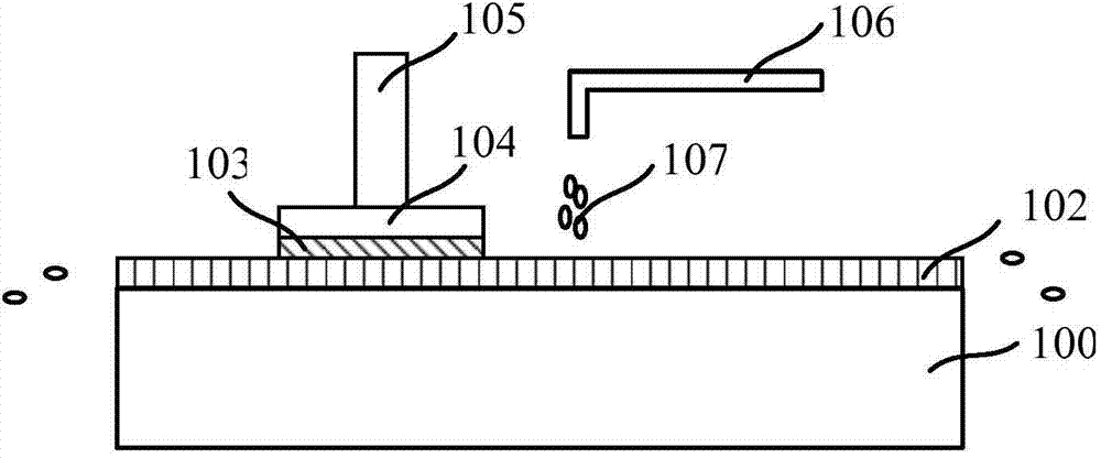
[0006] However, the existing chemical mechanical polishing device is easy to scratch the wafer when polishing the wafer, and the performance of the chemical mechanical polishing equipment needs to be further improved

Method used


Image

  • Chemical mechanical grinding device and chemical mechanical grinding method
  • Chemical mechanical grinding device and chemical mechanical grinding method
  • Chemical mechanical grinding device and chemical mechanical grinding method

Examples


Embodiment Construction

[0035] As a consumable in the chemical mechanical polishing process, the abrasive liquid has a very important influence on the planarization effect of chemical mechanical polishing. The composition of the abrasive liquid generally includes abrasive particles and chemical additives. The microscopic process of chemical mechanical polishing basically consists of two processes. Composition: 1) Chemical process: chemicals in the polishing liquid react chemically with the layer to be polished on the surface of the wafer to form substances that are easier to remove; 2) Physical process: abrasive particles in the polishing liquid react with the surface of the layer to be polished Mechanical and physical friction removes substances generated by chemical reactions. The commonly used abrasive particles in existing polishing liquids are silica particles. Studies have found that silica particles present a negative zeta potential in chemical additives, while the surface of the polishing pad ...


PUM


Abstract

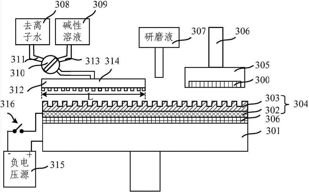
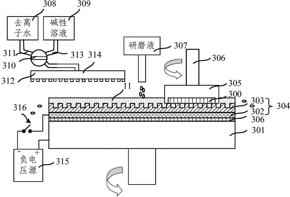
A chemical mechanical planarization (CMP) apparatus is provided. The CMP apparatus includes at least one platen; and a polishing pad disposed on the platen. The CMP apparatus also includes a polishing head disposed above the platen and configured to clamp a to-be-polished wafer; and a basic solution supply port disposed above the platen and configured to supply a basic solution onto a surface of the polishing pad. Further, the CMP apparatus includes a slurry arm disposed above the platen and configured to supply a polish slurry on the surface of the polishing pad; and a deionized water supply port configured to supply deionized water onto the surface of the polishing pad. Further, the CMP apparatus also includes a negative power source configured to apply a negative voltage onto the surface of the polishing pad.

Description

technical field [0001] The invention relates to the field of semiconductor manufacturing, in particular to a chemical mechanical grinding device and a chemical mechanical grinding method. Background technique [0002] In the present invention, with the rapid development of Ultra Large Scale Integration (ULSI), integrated circuit manufacturing techniques become more and more complex and sophisticated. In order to improve integration and reduce manufacturing costs, the number of components per unit area of ​​the chip is increasing, and planar wiring has been difficult to meet the requirements of high-density distribution of components. Multilayer wiring technology can only be used to utilize the vertical space of the chip to further improve the integration of devices. Spend. However, the application of multi-layer wiring technology will cause the surface of the silicon wafer to be uneven, which is extremely unfavorable for graphics production. For this reason, in order to re...

Claims


Application Information

Patent Timeline
Patent Type & Authority Applications(China)
IPC IPC(8): B24B37/04B24B37/34B24B57/00
CPCB24B37/04H01L21/30625B24B57/02B23H3/02B23H7/14B24B37/044B24B37/046B24B37/20B24B37/24B24D3/00H01L21/32115H01L21/3212H01L21/32125H01L21/67051H01L21/6715H05K3/07B24B37/10B24B37/34B24B53/017
Inventor 邓武锋
Owner SEMICON MFG INT (BEIJING) CORP
Learn More