Heat transfer type resistance box

A resistance box and heat transfer technology, which is applied in heat storage heaters, fluid heaters, lighting and heating equipment, etc., can solve problems such as unstable plasma equipment, affecting grid voltage stability, grid voltage fluctuations, etc., to achieve Avoid excessive current impact, save power, and avoid aging effects

Active Publication Date: 2015-07-01
安徽功率电气有限公司
View PDF7 Cites 1 Cited by
  • Summary
  • Abstract
  • Description
  • Claims
  • Application Information

AI Technical Summary

Problems solved by technology

[0004] Plasma equipment used in the field of domestic waste disposal or coal gasification generally has a large power. When used, it will cause fluctuations in the grid voltage, affect the stability of the grid voltage, and make the plasma equipment work unstable.

Method used


Image

  • Heat transfer type resistance box
  • Heat transfer type resistance box
  • Heat transfer type resistance box

Examples


Embodiment 1

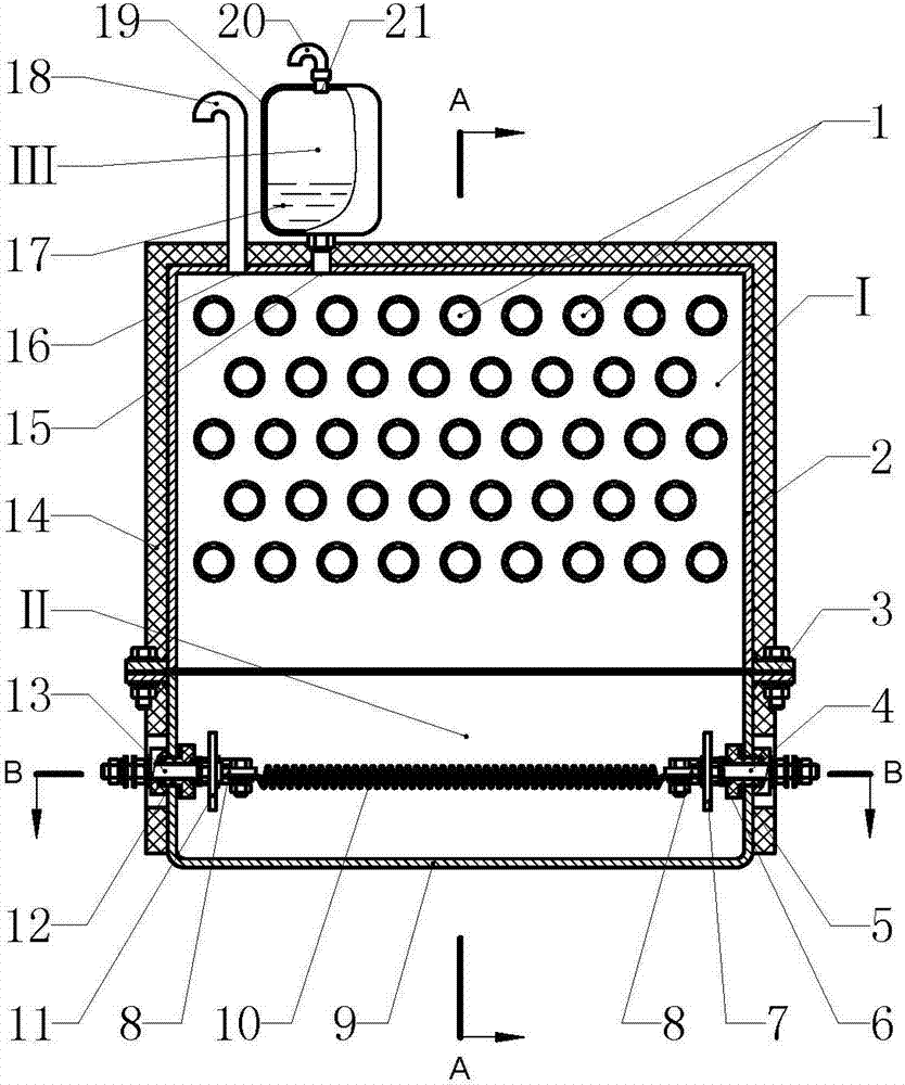
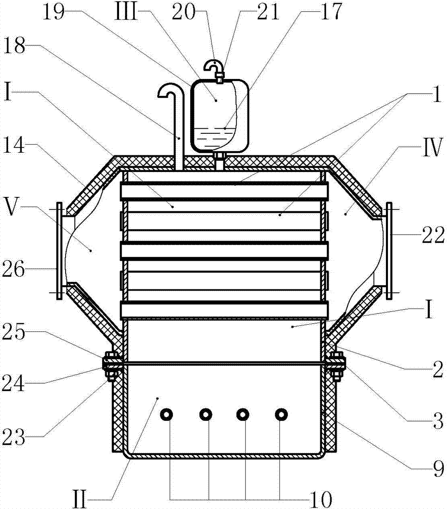
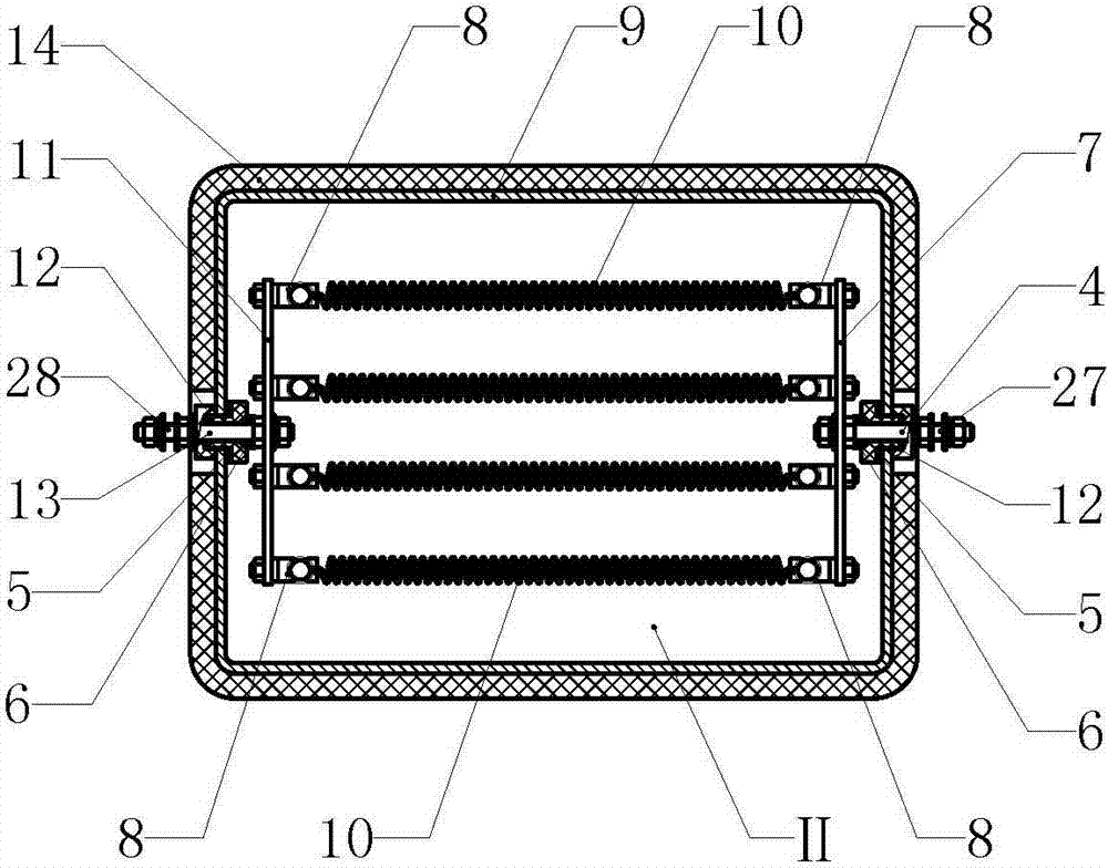
[0016] Example 1 figure 1In the embodiment shown, the heat transfer resistance box consists of an upper box (2), an air duct array (1), a lower box (9), a resistance wire (10), an incoming line assembly (13) and an outgoing line assembly ( 4) Composition, wherein the upper box (2) communicates with the lower box (9), the inner space of the upper box (2) constitutes the heat exchange area (I), and the air duct array (1) is arranged in the heat exchange area ( In Ⅰ), the air duct array (1) is formed by arranging multiple air ducts, and the two ends of each air duct pass through the walls on both sides of the upper box (2). The front air chamber (Ⅴ) has the rear air chamber (IV) on the right side of the upper box (2), and the front air chamber (Ⅴ) is connected to the rear air chamber (Ⅳ) through the space inside the duct array (1), The front air chamber (Ⅴ) is connected to the air inlet interface (26), and the rear air chamber (Ⅳ) is connected to the air outlet interface (22); t...


PUM


Abstract

The invention provides a heat transfer type resistance box and relates to electric heating equipment. The heat transfer type resistance box is composed of an upper box body, an air pipe array, a lower box body and a resistance wire. The upper box body is communicated with the lower box body, a heat exchange area is constituted by the inner space of the upper box body, the air pipe array is arranged in the heat exchange area, a front air chamber is arranged on the left side of the upper box body, a rear air chamber is arranged on the right side of the upper box body, and the front air chamber is communicated with the rear air chamber through intra-pipe spaces of the air pipe array. A heat transfer area is constituted by the inner space of the lower box body, the resistance wire is arranged in the heat transfer area, a front conductive support is arranged at the front end of the inner space of the lower box body and mounted at the inner end of a wire inlet assembly, a rear conductive support is arranged at the rear end of the inner space of the lower box body and mounted at the inner end of a wire outlet assembly, and the two ends of the resistance wire are connected to the front conductive support and the rear conductive support through mounting parts. The heat transfer type resistance box is used for high-power plasma equipment treating household garbage and enables network voltage to be stable and a plasma torch to work stably; heat of the resistance wire is transferred through heat conduction oil, and heat energy is recovered for drying garbage.

Description

technical field [0001] The invention relates to electric heating equipment, in particular to a plasma heating equipment. Background technique [0002] At present, plasma technology has been widely used, industrially used in plasma ignition, plasma spraying, metal smelting, plasma heating to manufacture nanomaterials, cutting, garbage incineration and waste treatment, etc. In recent years, the technology of using plasma to treat dangerous and harmful wastes and household garbage has developed rapidly. The plasma treatment method is quite different from the general incineration method. This state, accompanied by the discharge phenomenon, will generate active chemicals of excited atoms, excited molecules, dissociated atoms, free atomic groups, atomic or molecular ion groups, and their collisions with other chemical substances. In the plasma generator, the discharge effect causes the working gas molecules to lose the outer electrons and form an ion state, which generates high t...

Claims


Application Information

Patent Timeline
Patent Type & Authority Applications(China)
IPC IPC(8): F24H7/02F24H9/18
Inventor 周开根
Owner 安徽功率电气有限公司
Why Eureka
Try Eureka