Distributed gravity irrigation photovoltaic system for layer water lifting and energy storage

A photovoltaic system and distributed technology, applied in the direction of photovoltaic modules, photovoltaic power generation, photovoltaic power stations, etc., can solve the problems of reduced area occupied by photovoltaic panels, large occupied area, high energy consumption and high cost, and achieve small occupied area, Ultra-low power consumption, avoiding the effect of on-site guards

Active Publication Date: 2015-07-08
JIANGSU UNIV
View PDF7 Cites 20 Cited by
  • Summary
  • Abstract
  • Description
  • Claims
  • Application Information

AI Technical Summary

Problems solved by technology

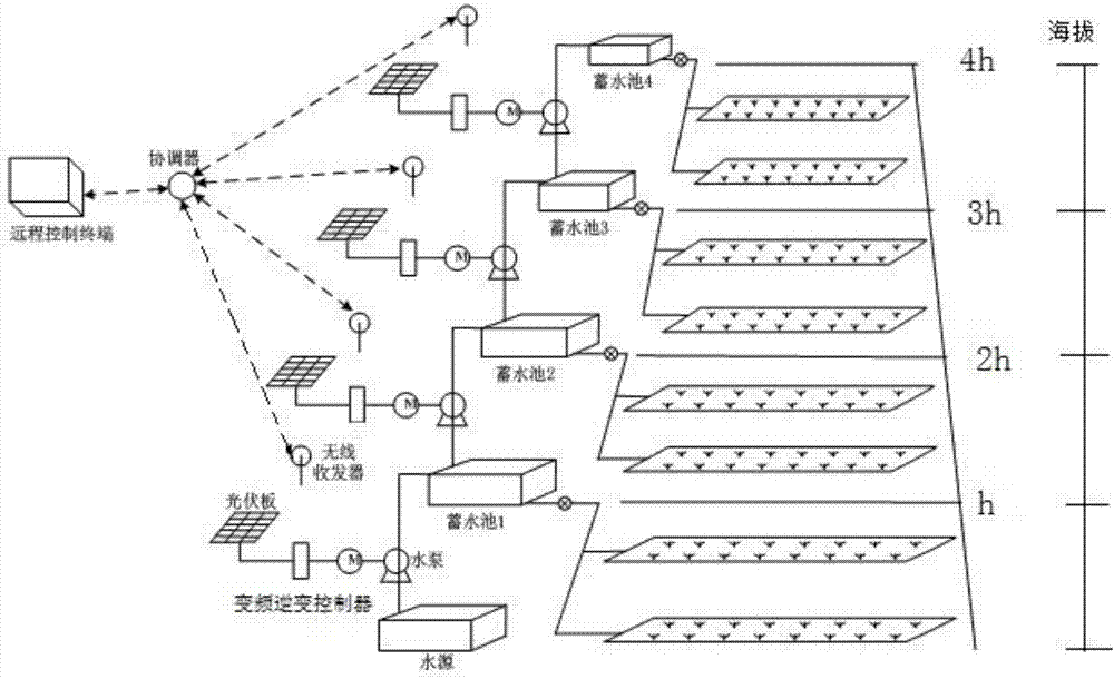
[0004] The purpose of the present invention is to provide a distributed self-pressurized irrigation photovoltaic system based on layered water extraction and energy storage in hilly and mountainous areas. The area is reduced, and the low-power water pump system is installed in layers at different elevations in the hilly area by using the elevation of the hilly area, so that the solar energy converted by the photovoltaic panel becomes the potential energy in the pool to achieve the purpose of energy storage. When irrigation is required, use The potential energy of the upper reservoir can self-pressure irrigate the crops in the lower layer to achieve the purpose of energy saving, and overcome the problems of large land occupation, high energy consumption and high cost in the agricultural irrigation system composed of centralized one-time water lifting technology.

Method used


Image

  • Distributed gravity irrigation photovoltaic system for layer water lifting and energy storage
  • Distributed gravity irrigation photovoltaic system for layer water lifting and energy storage
  • Distributed gravity irrigation photovoltaic system for layer water lifting and energy storage

Examples


Embodiment Construction

[0025] In describing the present invention, it is to be understood that the terms "upper", "lower", "front", "rear", "left", "right", "top", "bottom", "inner", "outer" ” and other indicated orientations or positional relationships are based on the orientations or positional relationships shown in the accompanying drawings, which are only for the convenience of describing the present invention and simplifying the description, rather than indicating or implying that the referred device or element must have a specific orientation, with a specific configuration and operation, and therefore should not be construed as limiting the invention.

[0026] In the present invention, unless otherwise clearly specified and limited, terms such as "installation", "connection", "connection" and "fixation" should be understood in a broad sense, for example, it can be a fixed connection or a detachable connection , or integrally connected; it may be mechanically connected or electrically connecte...


PUM


Abstract

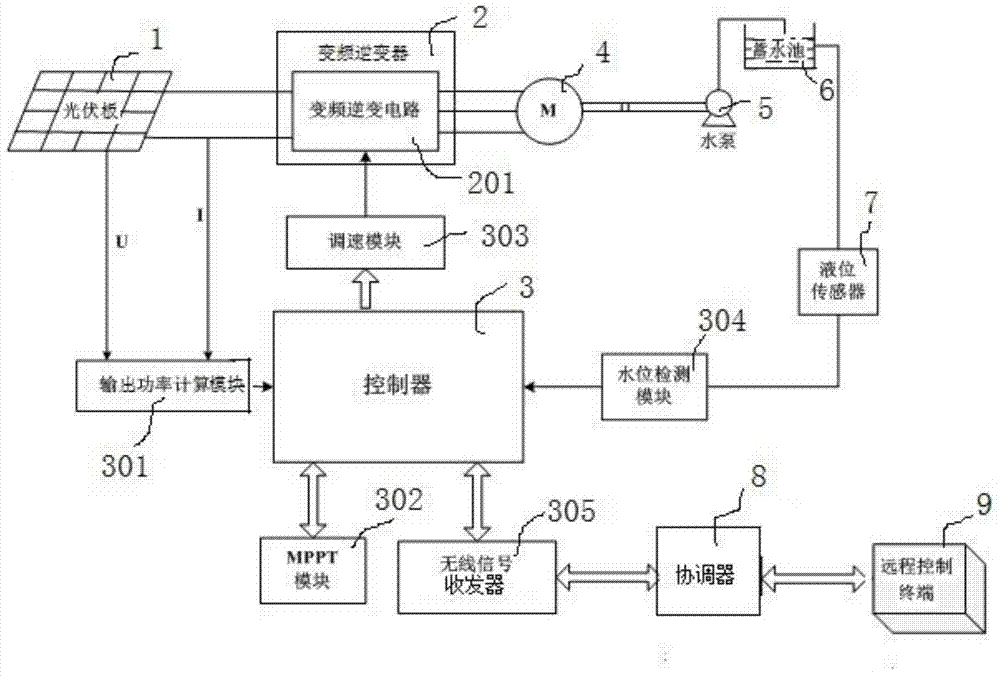
The invention belongs to the field of agricultural irrigation in hilly and mountain areas, and relates to a distributed gravity irrigation photovoltaic system for layer water lifting and energy storage. Hills are layered according to different altitudes, and each layer is provided with a photovoltaic pump system and is provided with a water storage tank; a photovoltaic plate is used for converting acquired solar energy into electric energy, a frequency conversion inverter is used for converting DC (Direct Current) voltage output by the photovoltaic plate into an AC (Alternating Current) voltage to drive a motor to operate, and a water pump is driven to pump water at a low water level to an upper water storage tank for storage by the motor; the system is used for storing the converted electric energy into the potential energy of water by using the difference of elevation of the hills, so as to realize layer water lifting and energy storage; furthermore, each layer of photovoltaic pump system is used for detecting the water level of the upper water storage tank by a liquid level sensor, and transmitting a water level signal to a remote control terminal through a wireless network, so as to prevent field watching and realize time saving and labor saving; in addition, the photovoltaic panel is small in floor area, low in lift and flexible and convenient to use; meanwhile, the electric energy storage cost is low, and the energy-saving irrigation can be effectively realized.

Description

technical field [0001] The invention relates to the field of new energy utilization and agricultural irrigation, in particular to a distributed self-pressurized irrigation photovoltaic system for layered water extraction and energy storage. Background technique [0002] At present, with the increasing shortage of energy and the deterioration of the environment, the development and utilization of green and clean energy provides an effective way to solve the global energy and environmental crisis, and solar energy is one of the most reliable clean energy to be developed and utilized at present. Most crop irrigation systems in my country use traditional diesel engines or power grids as power sources, which not only has high system costs, but also easily causes pollution to the environment. The photovoltaic water pump system that has emerged in recent years mainly uses centralized one-time water pumping technology to form an agricultural irrigation system. Due to the high power ...

Claims


Application Information

Patent Timeline
Patent Type & Authority Applications(China)
IPC IPC(8): A01G25/16H02S10/00G05F1/67G05B19/418G08C17/02
CPCY02E10/50Y02P60/12
Inventor 汤跃肖妹汤玲迪
Owner JIANGSU UNIV
Why Eureka
Try Eureka