Hot metal tank slag removal system and hot metal tank slag removal method

A technology for molten iron tanks and molten iron, which is applied in mechanical cleaning, manufacturing tools, metal processing equipment, etc., can solve the problems of eddy current entraining slag to the depths of molten iron, endangering the personal safety of operators, and being unable to be scraped out by a slag scraper. Achieving the effect of shortened slag removal time, shorter operation time, lower equipment cost and maintenance cost

Active Publication Date: 2017-09-01
WISDRI ENG & RES INC LTD
View PDF3 Cites 0 Cited by
  • Summary
  • Abstract
  • Description
  • Claims
  • Application Information

AI Technical Summary

Problems solved by technology

The patent with the application number of 201120551436.1 discloses a blowing slag removal device. The slag removal gun does not extend into the molten iron, but blows air directly on the liquid surface of the molten iron. The slag force is weak and the slag is not easy to gather at the mouth of the tank. If the blowing flow rate is small, the effect of slag removal will not be achieved; if the blowing flow rate is large, it will easily cause eddy currents to engulf the slag to the depth of the molten iron and cannot be removed by the slag remover. In turn, the cleanliness of the molten iron is poor, and the molten iron splashes, burns the tip of the gun and even endangers the personal safety of the operator.
[0004] In addition, the arrangement of the slag removal device in the prior art adopts the method of extending the gun head from above the stirring position (where the molten iron tank is located when the molten iron is desulfurized), and the gun head must pass through the dust removal pipeline, which is not easy to install and affects the dust removal effect

Method used


Image

  • Hot metal tank slag removal system and hot metal tank slag removal method
  • Hot metal tank slag removal system and hot metal tank slag removal method
  • Hot metal tank slag removal system and hot metal tank slag removal method

Examples


Embodiment Construction

[0034] The technical solutions in the embodiments of the present invention will be clearly and completely described below in conjunction with the accompanying drawings in the embodiments of the present invention. Obviously, the described embodiments are only a part of the embodiments of the present invention, rather than all the embodiments. Based on the embodiments of the present invention, all other embodiments obtained by those of ordinary skill in the art without creative work shall fall within the protection scope of the present invention.

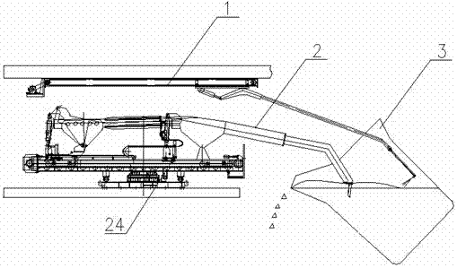
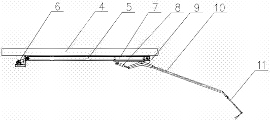
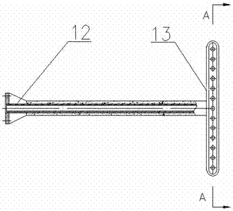
[0035] Such as Figure 1-Figure 7 , The embodiment of the present invention provides a slag removal system for a molten iron tank, which includes an air blowing and slag removal device 1 and a slag removal device; the slag removal device includes an operating table, a motion track provided on the operating table, and Mucking Machine 2 moving on the track. The air blowing and slag removal device 1 includes an air blowing and slag removal ...


PUM

PropertyMeasurementUnit
angleaaaaaaaaaa

Abstract

The invention relates to a slag removal system for a molten iron tank, comprising an air blowing slag removal device, the air blowing slag removal device includes an air blowing slag removal gun and a positioning mechanism for positioning the position of the air blowing slag removal gun; the air blowing slag removal gun Comprising a gun head, the gun head includes a hollow gun barrel, a gas distributor connected to the gun barrel and a plurality of nozzles, the gas distributor includes an arc cavity, and the plurality of nozzles are along the inner arc of the arc cavity The surfaces are arranged at intervals, and the blowing direction of each nozzle is in the same plane, which has an included angle with the length direction of the gun barrel. The present invention also relates to a method for removing slag from a molten iron tank, which uses the above-mentioned system for removing slag from a molten iron tank. The slag removal system and method provided by the invention have short operation time, low iron loss, and can reduce the air blowing volume, so the operation cost is low, and the slag removal work is safer and more reliable.

Description

Technical field [0001] The invention relates to the technical field of molten iron pretreatment, in particular to a molten iron tank slag removing system and a molten iron tank slag removing method. Background technique [0002] Desulfurization of molten iron is a necessary part of the steelmaking process. After the desulfurization of molten iron, a large amount of slag floats on the surface of the molten iron. Fast slag removal can shorten the desulfurization cycle, gain time for other links in the steelmaking cycle, and reduce the labor of operators. Improving the cleanliness of slagging can reduce sulfur back and improve the desulfurization effect. Reducing the iron loss of desulfurization slagging can save production cost and improve efficiency. Therefore, inventing a method for rapid slag removal, which can improve the cleanliness of slag removal and reduce iron loss at the same time, has a very positive significance for improving the quality of steel products and improvin...

Claims


Application Information

Patent Timeline
Patent Type & Authority Patents(China)
IPC IPC(8): B22D43/00C21C1/02
Inventor 袁金生黄俊王少强张文封伟华
Owner WISDRI ENG & RES INC LTD
Why Eureka
Try Eureka