A Dividable Combined Turning, Milling and Boring Machine

A combined and indexing technology, which is applied to other manufacturing equipment/tools, metal processing machinery parts, precision positioning equipment, etc., can solve the problems of difficult to guarantee accuracy, high work intensity, high manufacturing cost, etc., and achieve processing accuracy assurance and improvement Production efficiency and the effect of shortening the construction period

Active Publication Date: 2016-02-03
FOSHAN XINCHENG HONGDING MACHINERY TECH CO LTD
View PDF3 Cites 0 Cited by
  • Summary
  • Abstract
  • Description
  • Claims
  • Application Information

AI Technical Summary

Problems solved by technology

This method is not only labor-intensive, but also labor-intensive, especially for workpieces with large diameters, manual graduations are not accurate, resulting in high manufacturing costs, low accuracy and precision
[0003] For example, the processing of the vertical ribs of the lower frame of the large hydroelectric generator set, the boring processing of the pin holes of the joint surface of the runner, the processing of the vertical ribs and grooves of the rotor bracket, etc., these large and extra-large parts often have a diameter of 10 Meters or more than 20 meters, weighing 300 tons or even more than 500 tons, traditional methods rely on flame baking, manual grinding, manual calibration, or use many gaskets for on-site adjustment, which is not only time-consuming, but also difficult to guarantee accuracy

Method used


Image

  • A Dividable Combined Turning, Milling and Boring Machine
  • A Dividable Combined Turning, Milling and Boring Machine
  • A Dividable Combined Turning, Milling and Boring Machine

Examples


Embodiment 1

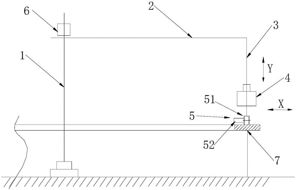
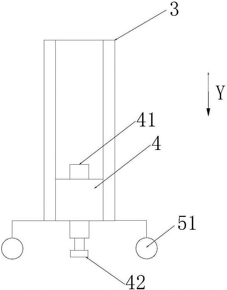
[0030] Such as Figure 1~3 As shown, the indexable combined turning milling boring machine of this embodiment includes a positioning shaft 1, a beam body, a power head 4, a traction device 5, an indexing detection device 6 and an indexing control device (not shown).

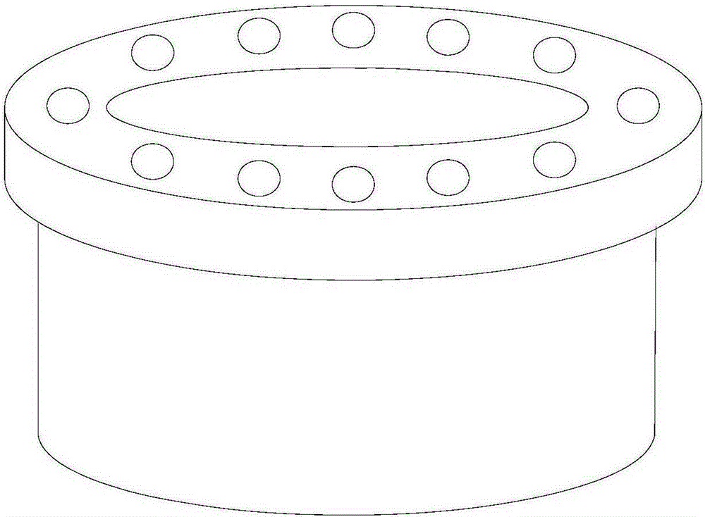
[0031] The workpiece 7 to be processed is a cylindrical body with a ring-shaped end face and a diameter of 13 meters. The positioning axis 1 is fixed on the central axis of the workpiece 7 to be processed. The beam body includes a beam 2 and a longitudinal beam 3. The beam 2 is fixed on the positioning axis 1 in a horizontally rotatable manner. The transverse length of the beam 2 can be adjusted. The longitudinal beam 3 and the beam 2 The end of the detachably connected and parallel to the positioning shaft 1, the power head 4 is slidably arranged on the longitudinal beam 3, which includes a main driver 41, a cutting head 42 and a power box (not shown), the power head 4 can be It moves in two directions, horizon...

Embodiment 2

[0037] Such as Figure 4~6 As shown, the indexable combined turning milling boring machine of the present embodiment includes a positioning shaft 1, a crossbeam 2, a longitudinal beam 3, a power head 4, a traction device 5, an indexing detection device 6, and an indexing control device (not shown). ), indexing fixture 10 and ring guide rail 8.

[0038] The structure, connection mode and function of the positioning shaft 1, the beam 2, the longitudinal beam 3, the traction device 5, the index detection device 6 and the index control device are the same as those in the first embodiment.

[0039]The power head 4 is arranged on the middle part of the longitudinal beam 3, the power head 4 includes a main drive 41, a cutting head 42 and a power box (not shown), and the cutting head 42 can be horizontal (that is, the X direction shown in the figure) and vertical (that is, the Y direction shown in the figure) to move in two directions. In this embodiment, the main driver 41 is the m...

Embodiment 3

[0044] Such as Figure 7-8 As shown, the indexable combined turning milling boring machine includes a positioning axis 1, a beam 2, a longitudinal beam 3, a power head 4, a roller 51, an indexing detection device 6, an indexing control device (not shown), and a circular guide rail 8 And two fixed brackets 9.

[0045] The structure, connection mode and function of the positioning shaft 1, the beam 2, the longitudinal beam 3 and the index detection device 6 are the same as those in the second embodiment. The workpiece 7 to be processed in this embodiment is a stator frame, and the annular guide rail 8 is located inside the workpiece 7 to be processed.

[0046] In this embodiment, no traction device is provided, and the positioning shaft 1 drives the rotation of the beam 2 and the longitudinal beam 3 . The rollers 51 are directly arranged on the bottom of the longitudinal beam 3 .

[0047] The power head 4 is arranged in the middle of the longitudinal beam 3, and its structure...


PUM


Abstract

The invention relates to a separable combined turning / milling / boring machine. The separable combined turning / milling / boring machine is characterized by comprising a positioning shaft fixed in the position of the central axis of a workpiece to be machined, a beam comprising a cross beam, a power head arranged on the beam in a sliding manner and comprising a main driver, a power box and a cutting tool bit, an indexing detection device for detecting the angle of rotation of the beam, and an indexing control device for receiving information fed back by the indexing detection device and controlling the beam to stop at a specified angle, wherein the cross beam is horizontally and rotatably fixed on the positioning shaft; the power head is capable of moving in the horizontal and vertical directions. As the indexing detection device and the indexing control device are adopted to control indexing, the separable combined turning / milling / boring machine is high in indexing precision, convenient to operate, and full-automatic; the production efficiency is improved and the machining period is shortened; the separable combined turning / milling / boring machine is suitable for indexing machining and the like of large workpieces.

Description

technical field [0001] The invention relates to the field of mechanical processing, in particular to an indexable combined turning, milling and boring machine. Background technique [0002] For the processing of evenly distributed holes or grooves on the end face or outer peripheral surface of large ring-shaped and ring-like workpieces, the turning-milling-boring machines of the prior art are usually manually measured and indexed or manually configured. This method not only consumes manpower, but also has high work intensity, especially for workpieces with large diameters, the manual graduation is not accurate, resulting in high manufacturing costs and low accuracy and precision. [0003] For example, the processing of the vertical ribs of the lower frame of the large hydroelectric generator set, the boring processing of the pin holes of the joint surface of the runner, the processing of the vertical ribs and grooves of the rotor bracket, etc., these large and extra-large pa...

Claims


Application Information

Patent Timeline
Patent Type & Authority Patents(China)
IPC IPC(8): B23P23/02B23Q16/02
CPCB23P23/02B23Q16/021
Inventor 张国根
Owner FOSHAN XINCHENG HONGDING MACHINERY TECH CO LTD
Why Eureka
Try Eureka