
3D printing system for building engineering construction and positioning method of 3D printing system

A 3D printing and construction engineering technology, applied in the fields of architecture, building structure, building material processing, etc., can solve the problems of large area, complex assembly, difficult to add printing, etc., to reduce the floor space and reduce the cost of use , mobile flexible and convenient effect

Inactive Publication Date: 2015-07-08
徐晓冰
View PDF7 Cites 14 Cited by
  • Summary
  • Abstract
  • Description
  • Claims
  • Application Information

AI Technical Summary

Problems solved by technology

[0005] However, the applicant found through research that due to the large area occupied by the construction project, the dimensions and specifications of the three-dimensional control bracket are correspondingly large, the assembly during construction is complicated, and will be affected by terrain conditions. Track movement, easy to be limited by position, difficult to add printing in the architectural layout with more complex structures

Method used


Image

  • 3D printing system for building engineering construction and positioning method of 3D printing system
  • 3D printing system for building engineering construction and positioning method of 3D printing system
  • 3D printing system for building engineering construction and positioning method of 3D printing system

Examples


Embodiment 1

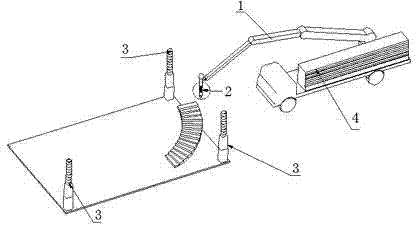
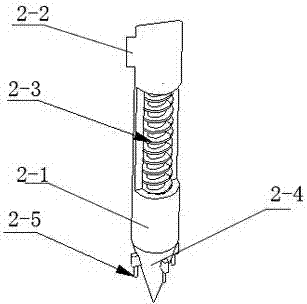
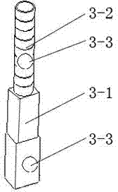
[0029] A kind of construction engineering construction 3D printing system provided by this embodiment, such as figure 1 As shown, it includes a multi-joint manipulator 1, a 3D printer printing extrusion head device 2, an ECU control unit, and at least three positioning rods 3 that are not in a straight line around the construction site. The handheld end of the multi-joint manipulator 1 is installed with a 3D printer printing extrusion The head device 2, the 3D printer printing extrusion head device 2 is equipped with a signal transceiver 2-5, and the positioning rod 3 is equipped with at least three positioning sources, the signal receiver is connected to the positioning source, and the signal of the positioning rod is transmitted The end is connected to the transceiver end of the ECU control unit, the driving end of the ECU control unit is connected to the controlled end of the multi-joint manipulator 1, and the ECU control unit contains:

[0030] The standard building device...


PUM


Abstract

The invention relates to a 3D printing system for building engineering construction and a positioning method of the 3D printing system. The 3D printing system comprises a multi-joint mechanical arm, a 3D printer head printing extrusion head device, an ECU and at least three positioning rods arranged on the periphery of a construction site and not located on the same straight line. A handheld end of the multi-joint mechanical arm is provided with the 3D printer head printing extrusion head device which is provided with a signal transceiver. At least three positioning sources are arranged on each positioning rod. The signal transceiver is in communication with the positioning sources. Signal transceiving ends of the positioning rods are connected with a transceiving end of the ECU, and a drive end of the ECU is connected with a controlled end of the multi-joint mechanical arm. The 3D printing system is high in flexibility and can conduct printing work on buildings of various complex layouts, and meanwhile the system is simple in structure, small in occupied area and convenient to assemble and use.

Description

technical field [0001] The invention relates to a 3D printing system and a positioning method thereof, in particular to a 3D printing system and a positioning method suitable for construction engineering construction, and belongs to the technical field of construction engineering construction. Background technique [0002] 3D printing is a kind of rapid prototyping technology. It is a technology based on digital model files and using bondable materials such as powdered metal or plastic to construct objects by layer-by-layer printing. [0003] 3D printing technology appeared in the mid-1990s and is actually the latest rapid prototyping device utilizing technologies such as light curing and paper lamination. The working principle of it is basically the same as that of ordinary printing. The printer is filled with "printing materials" such as liquid or powder. After being connected to the computer, the "printing materials" are superimposed layer by layer through computer contro...

Claims


Application Information

Patent Timeline
Patent Type & Authority Applications(China)
IPC IPC(8): E04G21/00E04G21/04
Inventor 徐晓冰
Owner 徐晓冰
Learn More