A cryogenic liquid storage tank lid system and cryogenic liquid storage tank

A technology for cryogenic liquid and storage tanks, which is applied in the field of cryogenic liquid storage tank cover systems and cryogenic liquid storage tanks. It can solve problems such as troublesome installation and gas loss, and achieve the effects of improved efficiency, easy installation, and convenient use.

Active Publication Date: 2016-08-17
TONGJI UNIV
View PDF6 Cites 0 Cited by
  • Summary
  • Abstract
  • Description
  • Claims
  • Application Information

AI Technical Summary

Problems solved by technology

But the evaporated gas is a loss after all
At the same time, there are a large number of cryogenic liquid storage tanks in use. It is also a very troublesome thing to install a refrigerator, because it involves transformation problems. Even if there is a refrigerator with high efficiency, it is very troublesome to install
Therefore, most cryogenic liquid storage tanks, such as liquid nitrogen, liquid argon or liquid oxygen storage tanks, can only vent the evaporated steam

Method used


Image

  • A cryogenic liquid storage tank lid system and cryogenic liquid storage tank
  • A cryogenic liquid storage tank lid system and cryogenic liquid storage tank
  • A cryogenic liquid storage tank lid system and cryogenic liquid storage tank

Examples


Embodiment 1

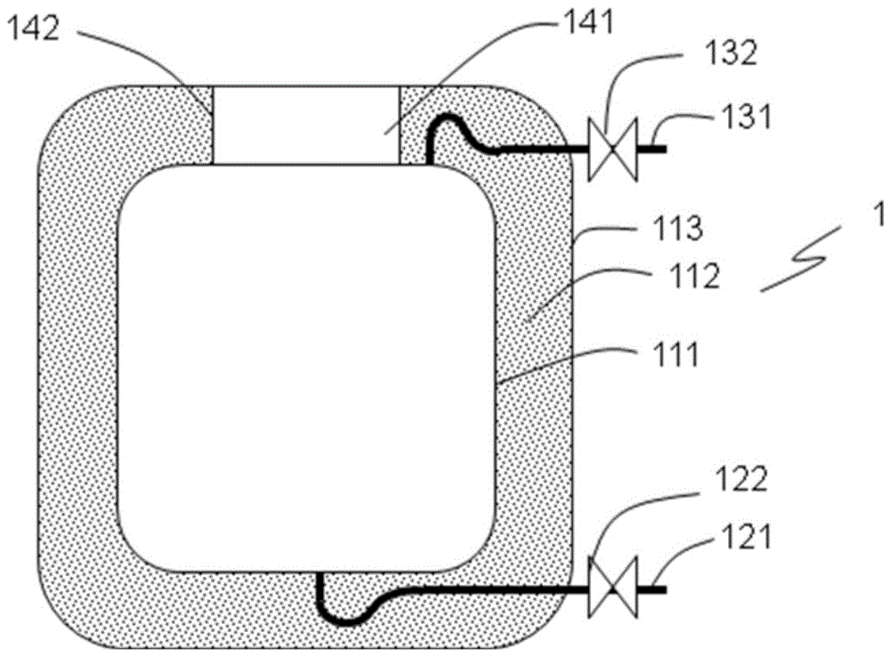
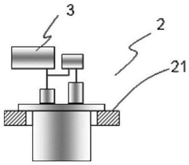
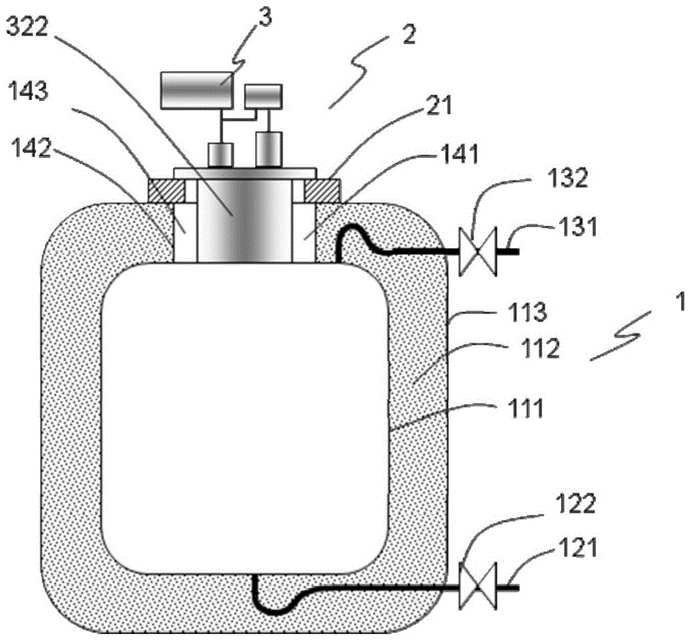
[0030] Cryogenic liquid storage tanks such as figure 1 , figure 2 , image 3 As shown, the cryogenic liquid storage tank body 1 and the lid system 2 are included.

[0031] Such as figure 1 , image 3 As shown, the cryogenic liquid storage tank body 1 is composed of a storage tank inner shell 111, a storage tank outer shell 113, and a storage tank insulation material 112 filled between the storage tank inner shell 111 and the storage tank outer shell 113. A storage tank liquid inlet pipe 121 and a storage tank steam outlet pipe 131 are provided. The storage tank liquid inlet pipe 121 is provided with a storage tank liquid inlet valve 122, and the storage tank steam outlet pipe 131 is provided with a storage tank steam valve 132. The storage tank thermal insulation material 112 is sandwiched between the storage tank inner shell 111 and the storage tank outer shell 113 to reduce heat leakage. The upper part has a storage tank opening 141, and the space in the inner shell 111 of the...

Embodiment 2

[0042] The difference from Embodiment 1 is that the refrigerator cover 322 is made of a low thermal conductivity material such as a foam material, such as Figure 7 Shown.

Embodiment 3

[0044] The difference from Embodiment 1 is that there is no refrigerator cover in the low temperature part 30, such as Figure 8 As shown, a large heat leakage loss may occur at this time, which will cause condensation and ice on the tank cover, causing corrosion problems.


PUM


Abstract

The invention relates to a low-temperature liquid storage tank cover subsystem and a low-temperature liquid storage tank, wherein the cover subsystem arranged on the low-temperature liquid storage tank includes a storage tank cover and a pulse tube refrigerator; the pulse tube refrigerator is arranged on the storage tank cover and includes a low-temperature part and a room-temperature part; the low-temperature part includes a cooler, a heat regenerator, a cold energy heat exchanger and a pulse tube which are connected in order; the cooler and the pulse tube are connected with the room-temperature part; the room-temperature part compresses gas to generate a pressure wave, the gas is expanded at the bottom of the pulse tube for refrigeration, the expansion work is recovered by an expansion work recovery device of the room-temperature part, steam is condensed into a liquid on the cold energy heat exchanger, and the liquid flows back to the low-temperature liquid storage tank. Compared with the prior art, the pulse tube refrigerator is mounted in the low-temperature liquid storage tank cover subsystem and is equipped with the expansion work recovery device, and the efficiency is improved, so that recondensed evaporation gas is profitable, and the cover subsystem can be applied in the widely-used low-temperature liquid storage tank.

Description

Technical field [0001] The invention relates to a low-temperature equipment, in particular to a low-temperature liquid storage tank cover system and a low-temperature liquid storage tank. Background technique [0002] Cryogenic liquid storage tanks are used to store cryogenic liquids, such as liquid helium, liquid hydrogen, liquid nitrogen, and liquefied natural gas. Due to heat leakage, part of the gas is always vaporized. In order to reduce evaporation, a cryogenic refrigerator can be used to recondense the evaporated gas. Early refrigerators used GM refrigerators, which had very low cooling efficiency and were rarely used except for liquid helium storage tanks. Compared with the GM refrigerator, the cooling efficiency of the newly developed pulse tube refrigerator has been greatly improved, but the efficiency is still too low. The gas released by evaporation is still small compared to the electricity cost of the pulse tube refrigerator. But the vaporized gas is a loss afte...

Claims


Application Information

Patent Timeline
Patent Type & Authority Patents(China)
IPC IPC(8): F17C1/12F17C13/04F25B9/14
Inventor 朱绍伟
Owner TONGJI UNIV
Why Eureka
Try Eureka