Waste heat two-stage recovery type split steam generator

A technology for steam generation device and waste heat recovery, which is applied in steam generation, steam boilers, removal of solid residues, etc.

Inactive Publication Date: 2016-07-06
CHINA UNIV OF PETROLEUM (EAST CHINA)
View PDF7 Cites 0 Cited by
  • Summary
  • Abstract
  • Description
  • Claims
  • Application Information

AI Technical Summary

Problems solved by technology

[0003] At present, oilfield steam injection generating devices matching the onshore heavy oil oilfield thermal recovery technology have appeared, and have been tested and applied in oilfields such as Xinjiang, Liaohe, and Shengli. The steam injection generating device has the characteristics of too large volume, heavy weight and complicated supporting process, and the offshore oil field platform is limited by the space cost, making it impossible to directly transplant and apply
Looking at the thermal reco...

Method used


Image

  • Waste heat two-stage recovery type split steam generator
  • Waste heat two-stage recovery type split steam generator
  • Waste heat two-stage recovery type split steam generator

Examples


Embodiment Construction

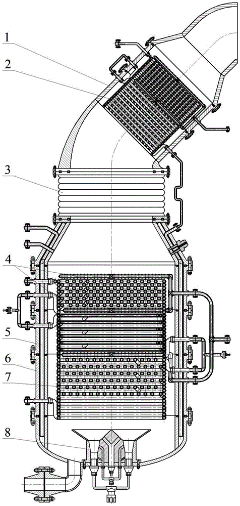
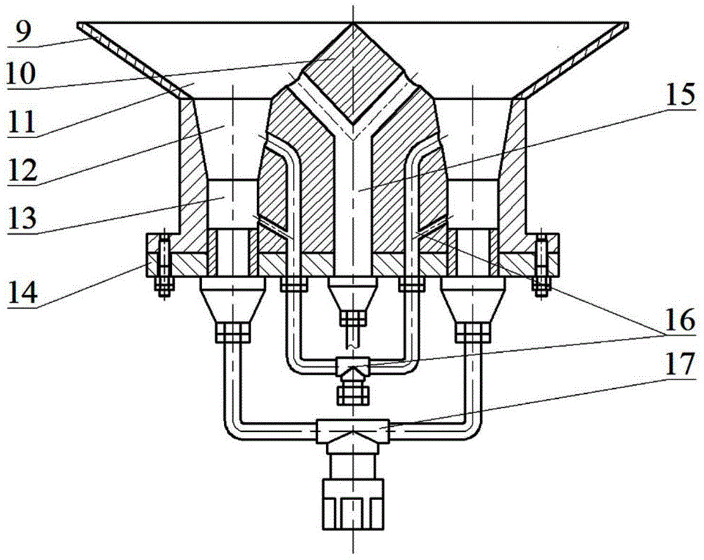
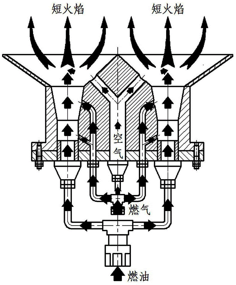
[0041]exist figure 1 Among them, the waste heat two-stage recovery type split steam generator consists of waste heat recovery device 1, secondary heat medium device 2, expansion joint 3, shower 4, primary cooler 5, combustion body 6, steam generating folded pipe 7, Composed of oil and gas dual burner 8 and steam generation control system. When assembling, first fix the oil-gas dual burner 8 to the middle part of the outer seal body of the combustion body 6 through the double combustion disc; The upper lower spray branch pipe, the middle cylinder and the middle folding pipe, the middle lower spray branch pipe, the upper cylinder and the upper folding pipe, and the upper lower spray branch pipe of the device 4; then the cooling pipe of the primary cooler 5 is arranged on the combustion body 6 and insert into the inner and outer cylinders; then connect the expansion joint 3 and the waste heat recovery device 1 in sequence, and arrange the thermal oil pipe of the secondary heat m...


PUM


Abstract

The invention provides a steam generating device. The steam generating device is that a split steam generator and an afterheat recovering device are integrally structured, so that the device is compact, easy to be maintained and small in smoke backpressure; an oil-gas double combustion device meets an oil-gas two-purpose mode according to an independent nozzle; short flame can be generated and uniformly distributed; a steam generating folding pipe is a layering disc type snake-shaped folding pipe which achieves efficient heat exchange under horizontal baffling and vertical reversing, so that the steam can be rapidly generated; in addition, the folding pipe has the excessive freshwater protection performance and can ensure reliable cooling and prevent the heating surface from salt deposit the folding pipe can be an inner threaded steel pipe to avoid film boiling of the freshwater; meanwhile, the a medium folding pipe is a double-layer pipe which avoids corrosion; a steam generation control system can automatically control the flow rate of mediums in the folding pipe and the oil-gas double combustion device and can protect the folding pipe from excessive temperature and excessive pressure; a first-stage cooler can achieve forced circulating liquid cooling of a combustion body and be matched with a second-stage heat medium device to achieve two-stage afterheat recovery; after spraying and purging, the smoke and ash can be regularly automatically cleaned.

Description

technical field [0001] The invention relates to a steam generating device for heavy oil platforms in the field of offshore oil engineering, in particular to a waste heat two-stage recovery type split steam generating device and its control system matched with thermal recovery and steam injection technology in offshore oil fields. Background technique [0002] At present, offshore oilfields have proven considerable heavy oil reserves, but heavy oil is extremely difficult to exploit due to its high content of heavy components, high viscosity, and poor fluidity. The research and application of thermal recovery and steam injection technology for heavy oil on offshore platforms has just begun Many aspects are immature or in the stage of sea trials, which have become the key factors restricting the economic and effective development of offshore heavy oil. Therefore, it is very necessary to carry out research on key technologies such as steam generation devices related to offshore ...

Claims


Application Information

Patent Timeline
IPC IPC(8): F22B31/00F22B31/08F23D17/00F22B37/10F22B35/00F23J3/00
Inventor 刘春花刘新福尹晓丽
Owner CHINA UNIV OF PETROLEUM (EAST CHINA)
Why Eureka
Try Eureka